


Servicios Personalizados
Revista

Articulo
 Inglés (pdf)
 Articulo en XML
 Referencias del artículo
 Enviar articulo por email
Indicadores
-
 Citado por SciELO
Links relacionados
-
 Similares en
SciELO
Similares en
SciELO
Compartir

 Permalink
Tecnia
versión impresa ISSN 0375-7765versión On-line ISSN 2309-0413
Tecnia vol.29 no.2 Lima jul. 2019
http://dx.doi.org/10.21754/tecnia.v29i2.719
10.21754/tecnia.v29i2.719
CONTRIBUCIONES ESPECIALES
A new seismic response control technique for buildings using block and tackle
Taiki Saito1
1 Department of Architecture and Civil Engineering, Toyohashi University of Technology, Toyohashi, Japan
ABSTRACT
The author proposed a new seismic response control system using a block and tackle (hereinafter, referred to as a dynamicpulley damper system) developed especially for the high-rise buildings. The proposed system has a configuration where adamper is installed on the track of the cable-stayed wire, amplifying the amount of movement of the wire by using a movablepulley that increases the damping effect to reduce the vibration of a building. we apply this system to connect the corestructure (parking tower) and the surrounding frame (housing part) of a high-rise building. This system aims to reduce theearthquake response of the building by the force of the damper attached to the core structure. To verify the effectivenessof this response control system, two types of shaking table tests were conducted; one is the large-scale shaking table testusing a magnetic damper, an-other one is the small-scale shaking table test using a steel damper. The mathematical modelof the dynamic pulley damper system to implement the frame analysis was developed and the results of simulation analysisare compared with the experiments.
Keywords: Response control, High-rise building, Block and tackle, Earthquake, Damper
INTRODUCTION
At the 2011 Great East Japan Earthquake, the high-rise buildings in Tokyo, Nagoya and Osaka swayedsignificantly and caused damage to non-structuralelements such as deformation of fire protection wallsand dropping of ceiling panels. To reduce building vibrationduring an earthquake, it has become popularin Japan to install vibration control devices such asoil dampers in high-rise buildings. Those dampers aregenerally installed inside the building frame to workagainst the shear deformation of the frame. However,since the lateral de-formation of the high-rise buildingcontains the large ratio of flexural component in theup-per stories, the dampers cannot work effectivelyto reduce the response of the high-rise buildings. Toovercome this problem, the various techniques havebeen developed including the application of TMD (TunedMass Damper) system [1].
The author proposed a new seismic responsecontrol system using a block and tackle (hereinafter,referred to as a dynamic pulley damper system) developedespecially for the high-rise buildings [2,3].
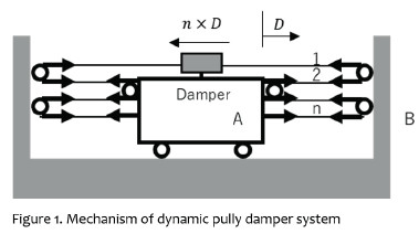
The proposed system has a configuration wherea damper is installed on the track of the cable-stayedwire, amplifying the amount of movement of the wireby using a movable pulley that increases the dampingeffect to reduce the vibration of a building. The principleof this mechanism is shown in Figure 1. The wireis stretched to reciprocate between the pulley groupsA and B, and one end of the wire is connected to thedamper. Wires and pulleys are arranged on the otherside of the damper under the same condition. Whenthe building moves during an earthquake, the amountof displacement D between A and B is enlarged by thenumber n of wires between them, and the dampercan move by n×D . At the same time, the damper forceis expanded n times and acts on the building. Theproposed system has a configuration where a damperis installed on the track of the cable-stayed wire, amplifyingthe amount of movement of the wire by usinga movable pulley that increases the damping effect to reduce the vibration of a building. Since the wire canbe stretched across distant parts of a building, thissystem is able to exert an effect on a large relative displacement.
A series of experimental studies on this systemhave been conducted to confirm the damping effect andevaluate the effect of the wire elongation and the frictionwith the pulley [4,5]. The features of this vibrationcontrol structure system are summarized as follows:
(1) It enables to increase the damping effect greatlyby amplifying the movement of the wire with respectto the deformation of the building.
(2) Even the damper with small capacity can be usedif the stroke of damper is large.
(3) Since the wire can be stretched between differentspans or different stories, various arrangementsare possible to install the system.
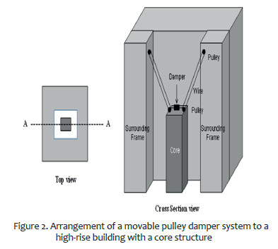
In this research, as shown in Figure 2, we considerapplying the dynamic pulley damper system to ahigh-rise condominium consisting of a surrounding frame(housing part) and a core part (parking tower). Thesurrounding frame and the core part are connected bya wire through pulleys and a damper device is installedat the top of the core. The relative displacement of twostructures is amplified by the movable pulleys, and thedamper moves largely to dissipate energy to reducethe vibration of the surrounding frame.
2. CONSTITUTIVE FORMULA
A force-deformation relationship of the dynamicpulley damper system considering elongation of thewire is derived below. It is assumed that stretchingdue to temperature change and deflection due to themass of the wire are ignored in the derivation.
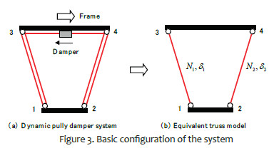
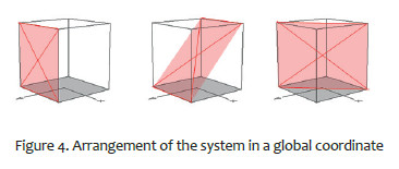
The following conditions are established whenimplementing a dynamic pulley damper system intoa frame. As shown in Figure 3, the wire is stretchedbetween the pulleys installed at any four points in theframe, and the wire of the diagonal part is reciprocatedbetween the pulleys to increase the movementof the damper installed at the top or bottom of thesystem. The wire and the damper are arranged in thesame plane in a global coordinate system, and theupper and lower sides of the wire are parallel to thehorizontal plane as shown in Figure 4.
For the left side of the system as shown in Figure 5, the force-deformation relationships of the wires in the oblique and horizontal parts are expressed as follows.
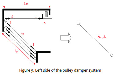
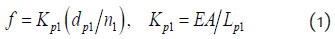
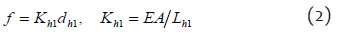
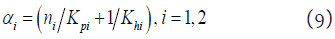
where, ∫ is the tension force of the wire, dp1, Lp1 , are the wire elongation and the pulley distance of the oblique part, η1 is the number of reciprocations of the wire in the oblique part, dh1, Lh1 are the wire elongation and the pulley distant of the horizontal part between the pulley and the damper, and E, A are the Young’s modulus and the cross section area of the wire. The force and deformation of the equivalent truss are
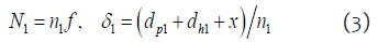
where, x is the deformation of the damper, δ1, N1 are the axial deformation and force of the truss.
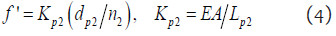
Similarly, for the right side of the system as shown in Figure 6, the force-deformation relationships of the wires in the oblique and horizontal parts are expressed as follows.
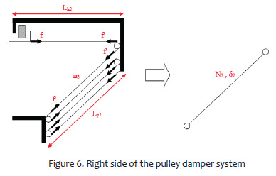

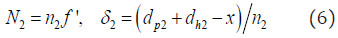
The force and deformation of the equivalent truss are
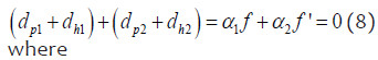
For the whole system as shown in Figure 7, the tension forces of the left and right wires act on the damper and the damper force is evaluated as
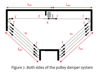
If one of the left and right wires stretches, the other wire shrinks by the same length, so the following relationship holds,
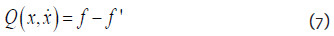
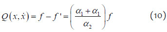
Therefore, the damper force Q is evaluated as
The force of the truss can be obtained from the force of the damper by the following equation.
The deformation of the damper is given by

Therefore, the procedure to implement into the frame analysis is
Step 1 Using the force N1 and displacement δ1 of the truss, find the deformation of the damper from Eq. (12).
Step 2 Determine the damper force Q(x) from the load deformation relationship of the damper.
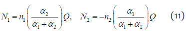
Step 3 Update the truss axial forces N1, N2 from Eq. (11)
The dynamic pulley damper is implemented in the computer program, STERA_3D [6], developed by one of the authors for three-dimensional earthquake response analysis of buildings.
3. SMALL SCALE SHAKING TABLE TEST
3.1 Outline of the Test Specimen
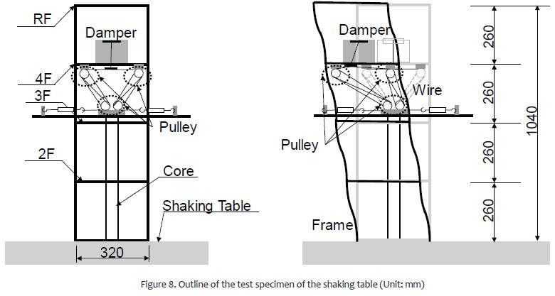
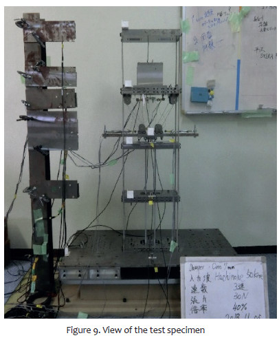
The outline of the test specimen for the shaking table test is shown in Figure 8. The specimen consists of two parts; a four-story frame part and a core part in the centre. The floor of the specimen is made of steel plates and the column is made of ultra-duralumin plates. A steel plate with 150 mm length and 2 mm thickness is used as a hysteresis damper. The damper is placed at the ceiling of the 3rd floor, and wires are connected at the end. The yield strength of the damper is about 14N. The initial tension of the wire is 30 N. The left side of Figure 8 represents the stationary state, and the right side represents the deformed state. The view of the specimen is shown in Figure 9.
3.2 Input Waves and Test Cases
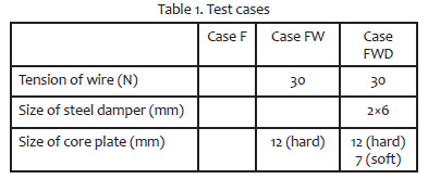
The conditions of the experiment are shown in Table 1. A model in which the frame part and the core part are not connected is [Case F]. A model in which the frame part and the core part are connected by wire and pulleys is [Case FW]. And a model in which a steel damper is introduced is [Case FWD]. In Case FWD model, the thickness of the core plate is changed as 12 mm (hard model) and 7 mm (soft model).
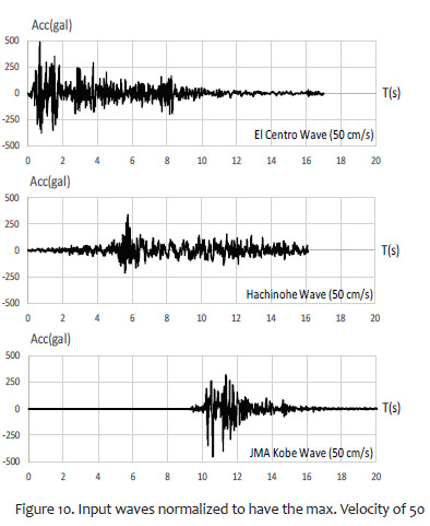
As input waves, we used three waves of 1940 El Centro wave, 1968 Hachinohe wave, and 1995 JMA Kobe wave, changing the original time scale 1/ 10 times to consider scale effect. Figure 11 shows the input waves normalized to have the maximum velocity of 50 cm/s. Figure 10 shows the input waves.
3.3 Test Results
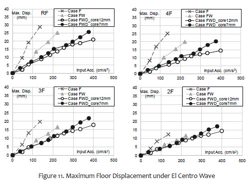
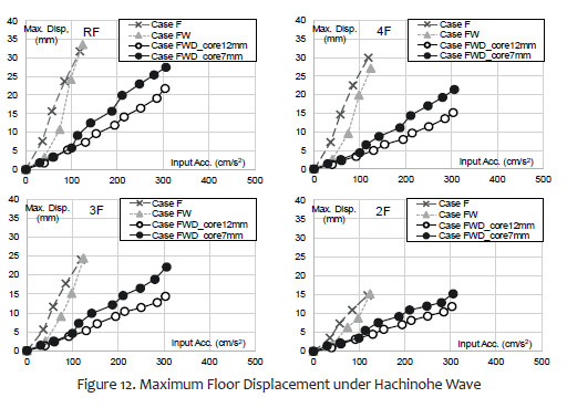
Figures 11 to 13 show the relationships between the maximum input acceleration and the maximum displacement at each floor of the specimen under El Centro, Hachinohe and JMA Kobe waves. The maximum displacement of each floor is obtained from the difference between the displacement of each floor of the specimen and the displacement of the shaking table.
In the case of El Centro wave in Figure 12, Case FW can suppress more building displacement than Case F.
There is no difference in damping effect between Case FW and Case FWD up to an acceleration of about 100 cm/s2 in the 3rd and 4th floors, and up to an acceleration of 200 cm/s2 in the 1st and 2nd floors. However, when the input acceleration is higher than 200 cm/s2, the damping effect of Case FWD is prominent.
In the case of Hachinohe wave in Figure 13, Case F and Case FW have similar damping effect. In Case FWD which introduced a damper, the deformation is suppressed both in the soft model and the hard model of the core part.
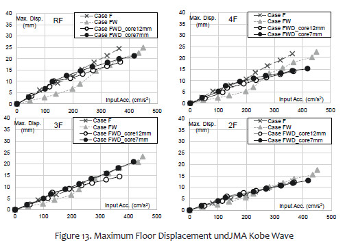
In the case of JMA Kobe wave in Figure 14, the difference of the damping effect under each ex perimental condition did not appear in the 1st and the 2nd floors. Moreover, even in the 3rd and 4th floors, the difference of damping effect does not appear in each experimental condition up to an acceleration of 200 cm/s2, and the damping effect of other two waves cannot be seen even if the acceleration is increased.
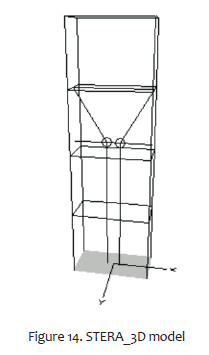
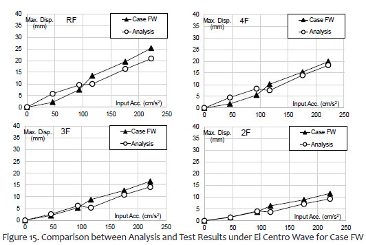
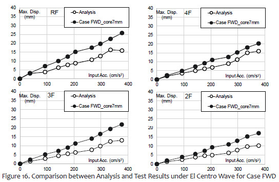
3.4 Simulation Analysis
Figure 14 shows the STERA_3D model for the simulation of test results. Figures 15 and 16 show the comparison of the maximum displacement between analysis and test results under El Centro Wave for Case FW and Case FWD, respectively. In case of Case (Figure 15), the analysis and test results correspond relatively well. On the other hand, in case of Case FWD (Figure 16), the analysis results are generally smaller than the test results. It means that the model of the damper device must be improved for the future study.
4. LARGE SCALE SHAKING TABLE TEST
4.1 Outline of the Test Specimen
The sectional view of the specimen is shown in Figure 17, and the full view photo is shown in the Figure 18. The specimen consists of a steel frame corresponding to the surrounding frame and a core part corresponding to the core structure, and a dynamic pulley damping system is attached between the steel frame and the core part. To set the natural period of the outer frame about 1 second, the weight was increased by loading a weight and the frame is supported by laminated rubber bearings. The weight of the specimen of the outer frame is 180 kN, and the natural period at the time of design is 1.25 sec.
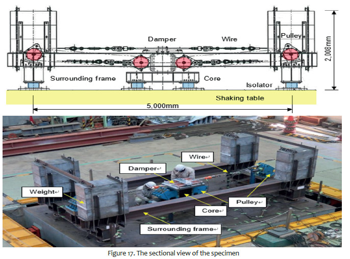

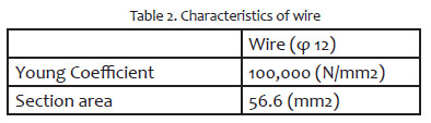
The dynamic pulley system is equipped with a pulley device capable of supporting from 0 to 6 grooves of pulley and the wire rope is constructed with filler type 6 × Fi (29) with a diameter of 12 mm, the tension of the wire is 10 kN (about 10% of the breaking load).
Acceleration and displacement of the specimen are measured with an accelerometer and a laser type displacement gauge attached to the outer surrounding frame portion, and the displacement of the center portion of the wire rope was measured with a wire displacement meter. The tension of the wire was measured by load cells installed at the pulley mounting portion at both ends of the wire and at the center of the wire.
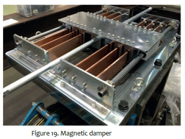
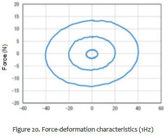
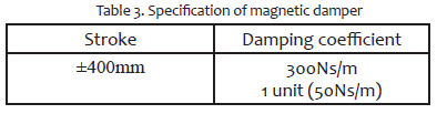
The test series were conducted with the magnetic damper produced by Sanwa Tekki Corporation. The magnetic damper has a linear characteristic with a damping coefficient of 300 Ns/m for 6 units (50 Ns/m for each unit) and the maximum stroke displacement is ± 200 mm. Figure 19 shows the view of the damper and Figure 20 shows the force deformation characteristics of the damper for one unit under 1Hz excitation. Table 2 shows the characteristics of wire and Table 3 shows the specification of magnetic damper.
4.2 Test Cases and Excitation Conditions
In the test, there are three cases of the number of wire loops around the pulleys: 1, 3, and 5, and two cases of base condition of the core structure: fixed base and non-fixed base sup-ported by laminated rubber bearings. The natural frequency of the surrounding frame is confirmed to be 0.98 Hz from the test without the wire and the damper.
The element test is a vibration test in one direction (X direction). Two types of excitation were carried out: random wave (with 0.5 to 30 Hz flat spectrum and 80 sec duration) and SINE wave excitation with the frequency of 0.98 Hz. Each vibration test was carried out by in-creasing gradually the level of excitation.
The first test series were conducted without the damper device to examine the friction between wire and pulley. The second test series were conducted with the magnetic damper.
4.3 Test Results
To make it easier to understand the analysis case, we use the schematic diagram as shown in Figure 21, where s d is the maximum displacement of the surrounding frame, c d is that of the core, and d d is the displacement of the damper.
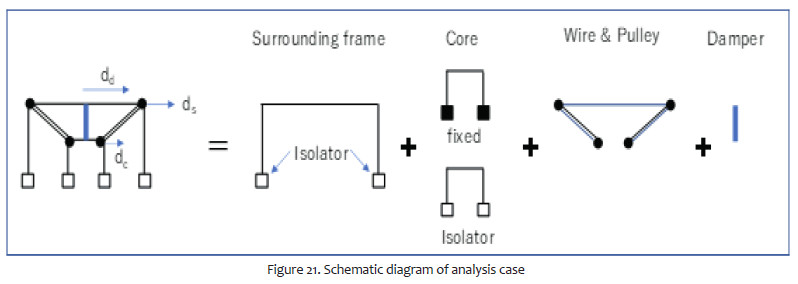
Figure 22 shows the maximum displacement responses of the surrounding frame for sine wave excitation and random wave excitation for loop number three. It is seen that the response of the surrounding frame can be reduced by simply setting a wire (red line). Adding a damper further reduces the response (blue line). Response reduction is greater when the core is fixed.

4.4 imulation Analysis
Figure 23 shows the STERA_3D model for the test specimen. Together with the damping force of the magnetic damper, the friction between wire and pulley is considered as a bilinear hysteresis damper.
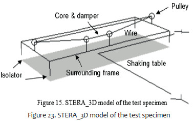
The friction force is assumed to be 0.3kN determined from the static loading test of wire and pulley.
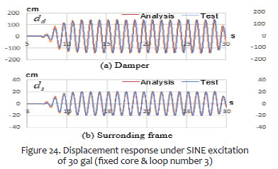
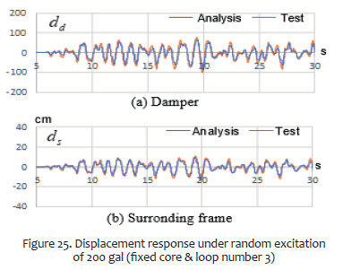
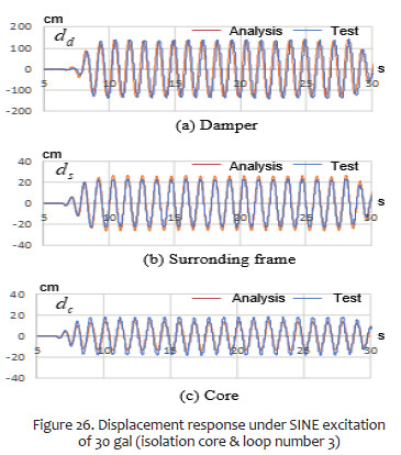
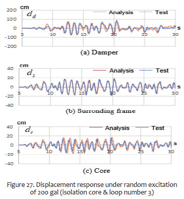
The displacement responses are compared between analysis and test results in Figure 24 to Figure 27. Both results are in good agreement.
CONCLUSIONS
• This paper proposed a new seismic response control system using a block and tackle, named as a dynamic pulley damper system. Two types of shaking table tests were conducted for the specimens simulating the core structure and the peripheral frame of a high-rise building. It was verified that the new system effectively reduced the building response. Also the analysis models using the constitutive formula developed in this study simulated the test results successfully.
REFERENCES
[1] H Kurino H, et al. 2017 Development of Large Tuned Mass Damper with Stroke Control System for Seismic Upgrading of Existing High-rise Building, 16th World Conference on Earthquake Engineering, Santiago Chile [ Links ]
[2] Saito T, et al. 2013 Proposal and Application of Seismic Control Structure using Block and Tackle System, Journal of Structural Engineering, 59 (B), (in Japanese) [ Links ]
[3] Saito T, et al. 2017 New Seismic Response Control System using Block and Tackle, 16th World Conference on Earthquake Engineering, Santiago Chile [ Links ]
[4] Denno S, et al. 2014 Seismic Control Structure using Block and Tackle System - Vibration Tests of Building Amplification Mechanism Damper Installation Parietal-, Journal of Structural Engineering, 60(B), Japanese [ Links ]
[5] Saito T, et al. 2019 Seismic Control Structure using Block and Tackle System - Element vibration experiment considering of an application to coupled vibration control system with a damper -, Journal of Structural Engineering, 65(B), Japanese [ Links ]
[6] Saito T STERA_3D, http://www.rc.ace.tut.ac.jp/saito/software- e.html [ Links ]
*Corresponding author:
Received: 12/08/2019
Accepted: 12/08/2019

