


Servicios Personalizados
Revista

Articulo
 Inglés (pdf)
 Articulo en XML
 Referencias del artículo
 Enviar articulo por email
Indicadores
-
 Citado por SciELO
Links relacionados
-
 Similares en
SciELO
Similares en
SciELO
Compartir

 Permalink
Tecnia
versión impresa ISSN 0375-7765versión On-line ISSN 2309-0413
Tecnia vol.29 no.2 Lima jul. 2019
http://dx.doi.org/10.21754/tecnia.v29i2.702
10.21754/tecnia.v29i2.702
CONTRIBUCIONES ESPECIALES
State of the art of DSRW test equipment subjected to side loads and equipment proposal for static testing at natural scale
Gram Rivas 1*, Elliot Quispe 1, Sandra Santa Cruz 2
1 GERDIS Researcher, Pontificia Universidad Católica del Perú, Lima, Perú.
2 Departamento de Ingeniería Civil, Pontificia Universidad Católica del Perú, Lima, Perú.
ABSTRACT
Dry stone retaining walls, DSRW, are low-cost traditional structures made of stones aimed to stabilize, support backfill and avoid soil erosion. They have massively been used as foundation of dwellings by vulnerable population located in the steeped hills surrounding some Latin-American cities. These walls are built following ancient techniques that are neither well studied nor formally established. Millions of people live in these conditions in seismic zones generating a high-risk situation. Experimental and numerical studies are needed in order to evaluate the reliability of low-cost DSRW and to validate or improve traditional techniques. The objective of this ongoing research is to design and construct a full-scale testing equipment to assess DSRW performance against lateral out-of-plane seismic forces. The methodology consists in the following steps: (1) Review of state-of-art of experimental testing of DSRW, (2) Analysis of failure modes of similar constructions (3) Conceptual and structural design of optimum full-scale testing equipment, (4) Construction planning (blueprints and budget) and (5) Construction and operation. Testing equipment found in technical literature can be classified into two groups according to the applied force: dynamic and static. Forces in dynamic tests are the result of acceleration imposed to the specimen, e.g. shaking tables and centrifuge machines. Forces in static testing are applied by hydrostatic pressure, lateral earth pressure, and specimen´s weight. Applied forces in dynamic tests simulate seismic forces well. On the other hand, it is a high cost solution and requires very specialized staff for operation and maintenance. Static alternatives are more affordable but seismic forces are roughly simulated by static forces. In this work a tilt table is proposed to test full-scale specimens. In this test, the specimen is built in a horizontal table that is slowly rotated. In this way, a static out-of-plane force acts in each particle of the specimen. The magnitude of the total force is the specimen´s weight multiplied by the sin of the rotating angle. Static test results could be conservative but they could give a good approach to understand DSRW damage accumulation process and failure. Two equipments were proposed: (1) tilting table for monotonic static test and (2) tilting table for cylic test. We compare costs, required area, construction feasibility, and operation manageability. We conclude that both of them are straightforward solutions to assess DSRW performance against out-of-plane lateral forces.
Keywords: DSRW, experimental test, full scale tests, lateral force, tilt table.
1. INTRODUCTION
In the city of Lima, more than 1 million people live on the hillsides in a situation of high seismic risk (Tarabochia, 2016). Their dwellings have been built informally over lands supported by Dry Stone Retaining Walls (DSRW). In Peru this walls, commonly called "pircas", are traditional constructions formed by stone blocks without mortar (Díaz, 2016).
DSRW have been used in many countries, some codes rule their construction, design and maintenance through the promulgation of regulations such as IS.14458 of India, the EM-7170- 14 of the US Department of Agriculture.
In countries where there is no regulation, you can find some private initiatives with government assistance such as CIRIA C676 in the United Kingdom or ENTPE in France. In other cases, there are civil groups which are in charge of preserving the vernacular technique of building stone walls in their area. Unfortunately, in Peru there is no regulatory control for this kind of constructions.
The Metropolitan Municipality of Lima has proposed a technique of improvement of DSRW that consists of applying a mixture of cement, lime and sand on the external face of the DSRW (MML, 2013). This technique has no scientific, analytical or empirical support reported; so it is urgent to study the performance of the DSRW subjected to out-of-plane loads caused by the lateral preassure of the landfill, the dwelling load and earthquake lateral forces, in order to propose risk reduction measures.
In the literature you can find multiple tests to study walls against static and dynamic out-of-plane lateral forces. The equipment for dynamic tests are: Centrifugal test, which subjects the specimen to centrifugal acceleration when turning it with respect to a central point (Fukumoto et al, 2014); pendulum frames, which subject the specimen to accelerations up to 2.64 g using an excavator to tilt an articulated base frame (Morris et al, 2017); and shaking tables that allow to introduce a movement in the base of the specimen corresponding to a seismic signal (Salvador, 2006; Ersubasi et al, 2010; Blondet, 2011; Cartagena et al, 2011; Carrillo et al, 2013). Static test use lateral forces from: hydrostatic preassure (Villemus et al, 2007), soil preassure (Colas et al, 2008; 2010a; 2010b; 2013; Mundell et al, 2010), and weight component of the specimen (Ceradini, 1992; Trujillo, 2007; Rincón, 2008; Restrepo-Vélez, 2009; Blondet, 2011; Valdez, 2012; Gutiérrez et al, 2013; Velazco, 2016). These equipments consists of tilting tables or platforms that allow to rotate the base of the specimen, generating a force on all the particles of the structure in the direction parallel to the rotated base, proportional to its own weight and to the angle turned (Rivas Sánchez, 2019).
2. EQUIPMENT FOR TESTING WALLS BEFORE PERPENDICULAR LOADS. STATE OF THE ART
In this section, wall test equipment for out of–plane loads are described, advantages and limitations of these equipment are discussed.
2.2 Centrifugal equipment (Fukumoto et al, 2014)
This equipment has dimensions of 796 x 440 x 500 mm and allows the specimen move describing a circular path with respect to a pivot center (Figure 1).
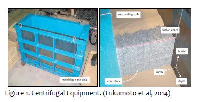
In this equipment, 1:33 scale models have been tested with cubic and wedge blocks. From these studies it has been concluded that the walls made with wedge blocks, have more resistance to seismic loads this is due to the increase in friction forces between the blocks and the filling due to the greater contact surface.
2.3 Pendulum frame (Morris et al, 2017)
The equipment consists of a pendulum frame with a joint in its base, the specimen is placed inside the frame and an excavator (which serves as an actuator) is used to balance the structure to simulate loads outside its plane equivalent to its own weight. the acceleration induced by heavy machinery. (Figure 2). This equipment has allowed to study the performance of adobe walls.
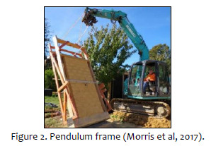
The tests were carried out on a real scale and the walls measure 3 to 4 meters high. The instrumentation used consists of: LVDT, portal gauges, accelerometers and go pro cameras. The test can be performed dynamically and statically. The wall must be quickly tilted dynamically. Static must be tilted very slowly the wall of 45 degrees back to 80 degrees forward, inclines at intervals of 10 to 15 degrees. The difficulties and limitations of the test are: the forces induced both statically and dynamically depend on the little manoeuvrability and control that allows the excavator and the skill of the operator of this machinery; and the induced accelerations are zero at the base of the wall and vary with the height, because it is necessary to fix it to the frame.
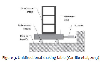
2.4 Shaking tables (Salvador, 2006; Ersubasi et al, 2010; Blondet, 2011; Cartagena et al, 2011; Carrillo et al, 2013)
A shaking table is a mobile platform that simulates the movements of an earthquake on a structural specimen, allows to introduce a movement in the base of the specimen corresponding to any registered seismic signal (Carrillo et al, 2013). The components of a vibrating table must meet certain requirements (Ramírez y Clavijo, 2001):
-Its platform must have sufficient stiffness and mass to minimize the effect of table-model interaction.
-It must have an isolation system to reduce the transmission of vibrations to the environment where the dynamic equipment is located.
-It must have an adequate fixing structure that guarantees a good support for the table.
The tables can reproduce movement up to 6 degrees of freedom: 3 movements and 3 rotations. There are tables for small scale and real scale tests (Blondet et al, 2011). The most economical and least complicated to operate are unidirectional tables (Figure 3).
This equipment uses hydraulic, mechanical or electromagnetic actuators to accurately reproduce a seismic movement satisfying the laws of similarity for the scaling of an input signal of displacement, acceleration or frequency, from one or more of its components or recorded accelerogram (Ramírez y Clavijo, 2001). Shaking tables can be characterized by: their dimensions, degrees of freedom, accelerations and maximum displacements, and by their carrying capacity. Table 1 shows some features of the most important shaking tables.
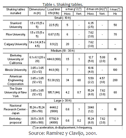
The shaking tables are very expensive experimental equipment, a table for real-scale tests can reach costs of up to 20 million dollars in its manufacture and 3 million dollars for its operation (Penzien et al, 1967).
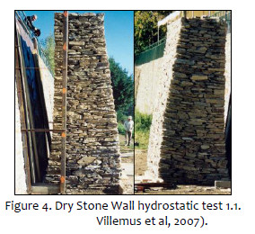
2.5 Test by hydrostatic pressures (Villemus et al, 2007)
This test requires an arrangement formed by a supporting wall and large bags filled with water that induce hydrostatic lateral loads to the walls tested. This arrangement has made it possible to carry out full-scale tests on stone walls with dry joints with heights of up to 4 meters (Figure 4). The instrumentation used consists of: 10 displacement sensors and monitoring using the stereophotogrammetry technique, which uses photographs and a stereoscope to obtain a false relief proportional to the displacements that have occurred.
2.6 Test by pushing granular material (Colas et al, 2010a;2010b; 2013)
This test requires an arrangement formed by formwork at both ends of the wall and cohesionless fill material that induces hydrostatic lateral loads to the specimens tested. This arrangement has allowed real-scale tests on stone walls with dry joints with heights of up to 2.5 meters. The instrumentation consisted of displacement sensors located in the central part of the wall and distributed throughout its height (Figure 5).
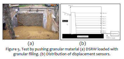
This test has allowed to identify two types of faults in the walls: by total turning with respect to its base and by sliding combined with local rotation of the stone blocks located in the lower third of the wall (Colas et al, 2010b).
2.7 Tilting equipment with screwjacks (Mundell et al, 2010)
This equipment consists of an articulated platform, 4 screwjacks or head screws and a steel frame; and subjecting the specimen to static lateral loads when tilting the platform by manipulating the screwjacks from a remote control board (Figure 6).
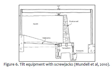
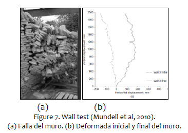
Fill soil has been placed to simulate active preassure. A hydraulic jack has been suspended from the steel frame and has allowed to simulate overloads on top of the filling (Figure 6). This equipment has allowed to evaluate the performance against lateral loads of 4 DSRW on a natural scale. Large deformations were observed in the walls without reaching the loss of stability, this occurs due to an internal rearrangement of the stone blocks. ( (a) (b) Figure 7).
2.8 Tilting table (Ceradini (1992), Restrepo (2004; 2009), Trujillo (2007), Rincón (2008), Blondet et al (2011), Valdez (2012), Gutiérrez et al (2013) y Velazco (2016).
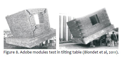
Tilting tables are equipment that allows the base of the specimen to rotate and use its own weight to generate a force on all the particles of the structure in direction perpendicular to the axis of rotation, proportional to its own weight and to the angle of the rotated angle. Tilt table tables are available for testing on a natural scale of up to 4x4 m and for small-scale tests of approximately 2x1 m. The experimental study of walls formed by blocks with dry joints has proved to be adequate to analyze failure modes of masonry structures with dry joints, since this material is composed of stones or bricks interlocked mainly by adhesion and friction (Ceradini, 1992). The first record of experimental tests on a natural scale with tilting tables comes from local research on adobe building systems in 1970 (Figure 8), where ways of reinforcing traditional adobe construction were studied, through vertical and horizontal reinforcement with cane (Zegarra et al, 2000; Blondet et al, 2011).
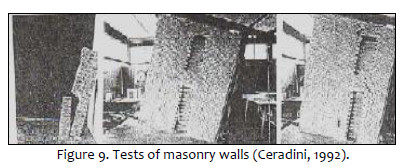
The work of Ceradini (1992), allowed to simulate distributed lateral forces depending on the mass on dry joint masonry on a real scale. The objective was to determine the mechanism of collapse and quantify the horizontal force that produces the fault. (Figure 9).
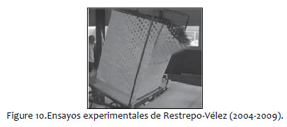
Subsequently, Restrepo-Vélez (2004; 2009) used similar equipment in stone models with dry joints to evaluate the resistance to collapse of various structural distributions of the masonry walls and compared them to each other (Figure 10). The difficulties of working with small-scale tests are mentioned, such as: finding materials with great specific weight and using factors of similarity for loads and structure responses.
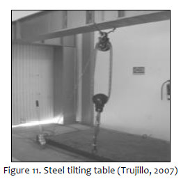
As part of a research campaign conducted at the University of Colima in Mexico, Trujillo (2007) and Rincón (2008) experimented with drywall gypsum blocks on a 2.44 m x 1.22 m steel tilting table. The lifting system consisted of cables and pulleys (Figure 11).
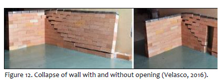
Also from the University of Colima highlights the work of Velazco (2016) who tested on the tilt table walls with and without opening, composed of blocks of wood (Figure 15). The walls have an "L" shape and presented failures due to turning at the base and torsion at the joints.
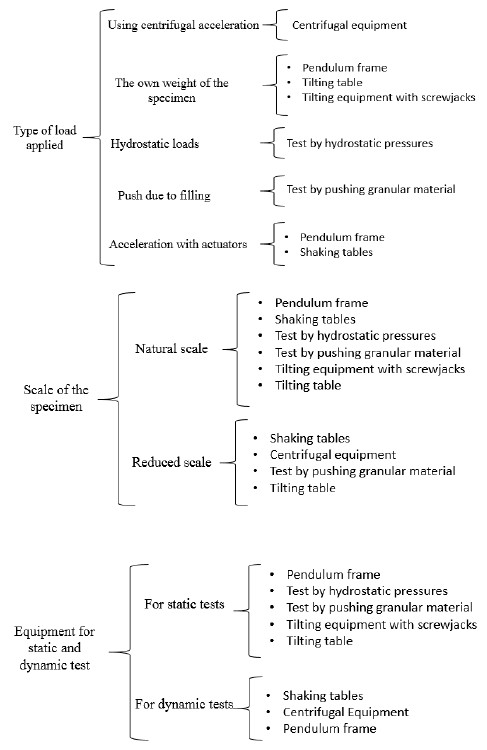
In summary, there are 7 alternatives for experimental tests of walls against lateral loads: centrifugal equipment, pendulum frame, vibrating table, equipment that uses hydrostatic pressures, equipment that uses thrust of granular material, tilt equipment with screwjacks and tilt table. Likewise, these experimental equipments can be classified according to various criteria, such as (Rivas Sánchez, 2019):
3. EXPERIMENTAL TESTING EQUIPMENT FOR DSRW: PROPOSAL
3.1 Preliminar analysis
Applied forces in dynamic tests simulate seismic forces well. On the other hand, it is a high cost solution and requires very specialized staff for operation and maintenance. Static alternatives are more affordable but seismic forces are roughly simulated by static forces. On the other hand, static tests bring the possibility to calibrate numerical model parameters of DSRW such as joint cohesion and friction in discrete element models DEM or finite elements models FEM, Static Monotonic tests could be useful to estimate capacity curves (shear base versus lateral displacement).
In this work, we propose to build a tilting table for static monotonic and cyclic tests (TTST) to study the parameters of numerical models and the effect of cycles of loading and unloading in DSRW
3.2 Design parameters
The main design parameters of the TTST are the maximum weight (30 ton), the maximum angle of inclination (45º) (Rivas Sánchez, 2019). In this section we will explain how these parameters were estimated.
Maximum Weight
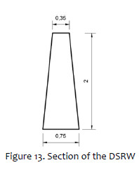
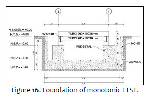
The maximum weight depends on the volume and specific weight of the DSRW to be tested and the filling to be used. The design weight is 30 tnf and it was obtained for a 2 m high pyramid (Figure 16), 4 m long and with a specific weight of 27.7 KN / m3; in addition, the weight due to the specific weight filling 16.4 KN / m3 was considered (Rivas Sánchez, 2019).
Maximum angle of inclination
From literature we have the following angles of inclination for which the walls tested failed in previous studies:
-
Trujillo (2007) : 26º-42º
-
Valdez et al. (2012) : 24º-47º
-
Gutiérrez et al. (2013) : 25º-38º
A design angle of 45 ° will be used, in such a way as to ensure a DSRW failure (Rivas Sánchez, 2019).
3.3 Monotonic TTST
3.3.1 Structural design
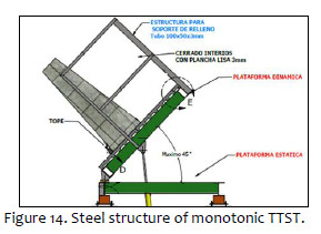
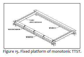
The steel structure of the monotonic TTST tilting table consists of a fixed platform, a mobile platform and a structure to support the filling (Figure 14). The fixed platform consists of W10x33 metal profiles and rectangular tubular sections type HSS-200mmx100mmx6 mm (Figure 15). The mobile platform consists of a cross-section of rectangular tubular sections type HSS-200mmx100mmx6 mm, HSS-100mmx100mmx3 mm, HSS-100mmx50mmx3 / 16 '' and W8x31 beams, in addition a fluted plate will be used to support the DSRW and evenly distribute its weight over the platform. The static and dynamic platforms are joined at a common end by a joint. The structure for support of filling is made up of rectangular tubular sections of HSS-100x50x3 mm, in addition a smooth inner plate of 3 mm will be used to contain the filling (Figure 14). All profiles are made of A-36 steel. The mechanical component will be supported by reinforced concrete pedestals that transmit the loads to the foundation.
Structural model
The modeling of the structure was carried out in the SAP 2000 program, considering the steel profiles as frame elements. The structural analysis was carried out for the dynamic platform considering the horizontal position and at 45º of inclination. The following loads were considered: dead load (CM): the own weight plus 80.0 kgf / m2, due to the weight of the fluted plate; and live load (CV): 30 tonf. Below are the design plans of the monotonic table (Figure 14 and Figure 15).
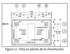
3.3.2 Foundation design
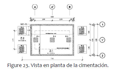
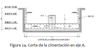
The equipment is going to be located in Lima on a stiff soil (4 kg/cm2). The equipment base consists in 6 square pedestals of reinforced concrete of f'c = 210 kgf / cm2 of 50 cm of side. The foundation is a reinforced concrete footing of f'c = 210 kgf / cm2 and 0.40 m of cant. The foundation was modeled using the SAFE software. Retaining walls (MC-15) were placed around the perimeter of the table (Figure 16).
A maximum pressure of 7.8 tonf / m2 = 0.78 Kgf / cm2 has been obtained, being less than the admissible amplified effort of 4 kg / cm2.
3.3.3 Hydraulic system
The monotonic table will be articulated on one of its sides, this side will remain fixed, the other end of the table will also rest on reinforced concrete pedestals, but at the same time on a hydraulic piston system. In this way, the hydraulic-electric component has the following elements and characteristics: two double effect hydraulic pistons of maximum force 15,000 kg each with stroke length: 1 m, a hydraulic pump with 2 HP motor. It is important to mention that the necessary voltage is 220V. These hydraulic pistons will be operated from a remote control board, which will allow controlling the lifting speed and increasing the angle of inclination at constant intervals; that is, you will have full control of the operation of the equipment.
3.3.4 Instrumentation
LVDT will be used to record the lateral displacements of the DSRW before the incremental static charges. An LVDT is a position sensing device that provides an alternating current output voltage proportional to the displacement of its core that passes through its windings. (Figure 18)
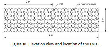
In this way 9 LVDT in total will be used, which will get the deformation of the wall before monotonic lateral loads. It is important to mention that, due to the hydraulic pistons and the control panel that will drive them, the angle of inclination will be measured automatically from the deployed length of the piston.
3.4 Cyclic TTST
3.4.1 Structural design
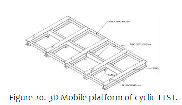
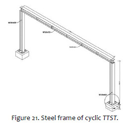
Steel structure is formed by a mobile platform, two steel frames, a platform and a lifting system (Figure 19). The mobile platform consists of a cross-section of rectangular tubular sections, HSS-200mmx100mmx6 mm, HSS-100mmx100mmx3 mm and W8x31 profiles. The platform is articulated along its central longitudinal axis and rests on a base structure formed by a beam W12x40 with stiffeners to control torsional problems. The steel frames are made up of two metal columns of W10X60 and a metal beam of W12X53.
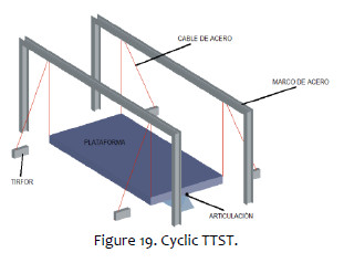
The structure for support of filling is the same as that proposed in the monotonic tilt table. The lifting system consists of 4 pairs of fixed and mobile pulleys and 4 electric winches of 5.45 tonf capacity. The same modeling, analysis and design considerations were taken as in the monotonic table (See Figure 20 and Figure 21).
3.4.2 Foundation
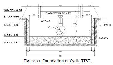
It consists in 3 square pedestals (P-1) of reinforced concrete f'c 280 kgf / cm2 of 50 cm side, which rest on a running shoe of reinforced concrete of f'c 280 kgf / cm2, of rectangular shape with dimensions 3.65 x5.05x0.40 m. Also, containment walls were specified to control the lateral earth pressure (Figure 22).
3.4.3 Lifting system
A cyclic tilting table with a lifting system similar to that used in the works of Trujillo (2007) and Rincón (2008) is proposed, but tirfor rigs must be replaced by electric winches since the latter have a greater load capacity. Winches are mechanical devices that are driven by an electric motor.
The lifting process would be as follows:
1st The two tirfores at one end of the table would pull the steel cables that are held from the pulleys fixed on the steel frame.
2nd. The cables are tied at the other end to two rings attached to the tilting platform of the table, making the latter tilt
3rd The process is repeated, but using the tirfores, pulleys, cables and rings at the other end of the TTST.
3.4.4 Instrumentation
The instrumentation is the same as that suggested for the monotonic tilt table. Because the cyclic table will not be tilted using hydraulic pistons, it is necessary to have an instrument to measure the angle of inclination. It is proposed to use the same measurement system of Trujillo (2007), which is made up of a rotary potentiometer, an 8.88 cm aluminum disc and a 1 "diameter steel rod.
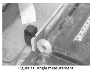
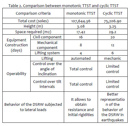
Table 2 presents a summary of the comparison criteria of the MIEE designs. It is necessary to have total control over the angle of inclination; therefore, the MIEE with monotonic movement is chosen as the optimal alternative to test natural scale pyramids against static lateral loads (Rivas Sánchez, 2019).
CONCLUSIONS
Two feasible alternatives to evaluate DSRW capacity for out-of-plane lateral loads are proposed: monotonic TTST and cyclic TTST. Both of them permit the, being a simple, efficient and economical equipment to test full scale DSRW against static lateral loads; since it allows to apply distributed loads using the own weight of the specimen. This equipment is feasible to build since it uses conventional materials and instruments. Two inclinable tables were designed: one for monotonic tests and another for cyclic tests. Both tilting tables have 3 components: mechanical, civil and lifting system. The monotonic table has an automated lifting system made up of hydraulic pistons operated from a remote control board. The cyclic table has a mechanical lifting system made up of pulleys, cables and electric winches. We compare costs, required area, construction feasibility, and operation manageability. We conclude that both of them are straightforward solutions to assess DSRW performance against out-of-plane lateral forces.
ACKNOWLEDGEMENT
This work has been partially funded by Aristotle Scholarship of the Graduate School of the Pontifical Catholic University of Peru and the Grant Project N ° 109-2017-FONDECYT-GYP.
REFERENCES
[1] Tarabochia M 2016 Diario La República, 4 de marzo.
[2] Fukumoto Y, Yoshida J, Sakaguchi H and Murakami A 2014 The effects of block shape on the seismic behavior of dry-stone masonry retaining walls. Soils and Found, 1117-1126. [ Links ]
[3] Morris H and Brooking J. 2017 Out of plane adobe wall veneer performance from a novel quasi-static and dynamic tilt test. New Zealand Society for Earthquake Engineering. [ Links ]
[4] Salvador E 2006 Comportamiento sísmico de un módulo de adobe de dos pisos con refuerzo horizontal y confinamientos de concreto armado. Tesis para optar el título de ingeniero civil. Pontificia Universidad Católica del Perú. Lima. [ Links ]
[5] Blondet M, Villa G, Brzev S and Rubiños A 2011 Earthquake- Resistant Construction of Adobe Buildings: A Tutorial. [ Links ]
[6] Cartagena C and Ramírez C 2011 Diseño, modelamiento y simulación de una mesa sísmica unidireccional hidráulica. Universidad Industrial de Santander. [ Links ]
[7] Villemus B, Morel J and Boutin C 2007 Experimental assessment of dry stone retaining wall stability on a rigid foundation. Engineering Structures, Elsevier. [ Links ]
[8] Colas A, Morel J and Garnier, D 2008 Yield design of dry-stone masonry retaining structures: Comparisons with analytical, numerical and experimental data. Int. J. Numer. Anal. Methods Geomech. 32 (14) 1817-1832. [ Links ]
[9] Colas A, Morel J, Garnier D 2010a 2D modelling of a dry joint masonry wall retaining a pulverulent backfill. Int. J. Numer. Anal. Methods Geomech. 34(12), pp 1237-1249 [ Links ]
[10] Colas A, Morel J, Garnier D (2010b). Full-scale field trials to assess dry-stone retaining wall stability. Engng Struct. 32 (5) pp 1215-1222 [ Links ]
[11] Colas A, Morel J, Garnier, D 2013 Assessing the two-dimensional behaviour of drystone retaining walls by full-scale experiments and yield design simulation. Geotechnique. [ Links ]
[12] Díaz A 2016 Estudio de Procesos de Automatización y Georreferenciación de Elementos Urbanos en Cuatro Agrupaciones Familiares de La Quebrada "El Progreso" Carabayllo – Lima, Perú [ Links ].
[13] Mundell C, McCombie P, Heath A, Harkness J and Walker P 2010 Behaviour of drystone retaining structures. Proc. Instn. Civ. Engrs Struct. Build. 163(1) pp 3-12 [ Links ]
[14] Municipalidad Metropolitana de Lima-MML 2013 Guía para la habilitación urbana en asentamientos humanos y mitigación del riesgo. Lima, Perú [ Links ]
[15] Ceradini, V 1992 Modellazione e sperimentazione per lo studio della struttura muraria storica. Ph. D. Tesis en historia y teoría de estructuras, Universidad de Roma "La Sapienza". [ Links ]
[16] Trujillo, L 2007 Estudio de bloques de yeso en mesa inclinable. Informe de investigación. Facultad de Ingeniería Civil, Universidad de Colima [ Links ]
[17] Rincón, R 2008 Estudio de muros de bloques de yeso en mesa inclinable. Informe de investigación. Facultad de Ingeniería Civil, Universidad de Colima [ Links ]
[18] Rivas G Y 2019 Diseño de equipo para ensayos de pircas ante cargas laterales estáticas. Tesis para optar el título de Magíster en Ingeniería Civil. Pontificia Universidad Católica del Perú. Lima [ Links ]
[19] Restrepo-Vélez, L and Magenes, G 2009 Static tests on dry stone masonry and evaluation of static collapse multipliers. Research Rep. ROSE 2009, pp 2-7 [ Links ]
[20] Penzien J, Bouwkamp J, Cloug R and Rea D 1967 Feasibility study large-scale earthquake simulator facility. Earthquake Engineering Research Center. Department of General Services State of California. EEUU [ Links ]
[21] Valdez, R 2012 Modelos de Muros de bloques ante cargas laterales. Universidad de Colima [ Links ]
[22] Gutiérrez M and Núñez D 2013 Mejoramiento de la Tecnología para la Construcción y Sistema de Difusión de la Vivienda Social Sismo-Resistente -TAISHIN – FASE II, Universidad de El Salvador. El Salvador. [ Links ]
[23] Velazco, M 2016 Comportamiento de muros en ángulo de mampostería con junta seca ante cargas laterales. Universidad de Colima [ Links ]
[24] Ersubasi F and Korkmaz H 2010 Shaking table tests on strengthening of masonry structures against earthquake hazard. Natural Hazards and Earth System Sciences, 10, pp 1209-1220. [ Links ]
[25] Carrillo J, Bernal N and Porras P 2013 Evaluación del diseño de una pequeña mesa vibratoria para ensayos en ingeniería sismo-resistente [ Links ]
[26] Restrepo-Vélez, L 2004 Seismic risk of unreinforced masonry buildings. Tesis. European school for advanced studies in reduction of seismic risk-ROSE School, Universidad de Pavia [ Links ]
[27] Turer, A 2004 Seismic performance improvement of masonry houses using scrap tires. World Bank DM2003, SPIM-1451 Project, Final Report. Ankara, Turkey [ Links ]
[28] Zegarra L, Bartolomé A, Quiun D and García G 2000 Reinforcement of existing adobe houses, in: Aridland Newsletters, Desert Architecture for a New Millennium 47 [ Links ]
[29] Clavijo J, Ramírez L 2001 Diseño, modelamiento y simulación de una mesa sísmica unidireccional hidráulica. Tesis para optar el título de ingeniería mecánico. Universidad Industrial de Santander. Colombia [ Links ]
[30] Grupo de Gestión de Riesgos de Desastres en Infraestructura Social y Vivienda de Bajo Costo-GERDIS 2018 Informe de caracterización de las propiedades físicas y mecánicas de pircas en una zona de laderas en el distrito de Carabayllo. Proyecto subvención Nº 109-2017-FONDECYT. Pontificia Universidad Católica del Perú-Lima [ Links ]
Corresponding author: grivass@pucp.edu.pe
Received: 29/06/2019
Accepted: 07/08/2019

