


Servicios Personalizados
Revista

Articulo
 Inglés (pdf)
 Articulo en XML
 Referencias del artículo
 Enviar articulo por email
Indicadores
-
 Citado por SciELO
Links relacionados
-
 Similares en
SciELO
Similares en
SciELO
Compartir

 Permalink
Tecnia
versión impresa ISSN 0375-7765versión On-line ISSN 2309-0413
Tecnia vol.29 no.2 Lima jul. 2019
http://dx.doi.org/10.21754/tecnia.v29i2.713
10.21754/tecnia.v29i2.713
SEISMIC PROTECTION SYSTEMS
Modeling, analysis and seismic design of structures using energy dissipators SLB
Luis Bozzo1, Helbert Gonzales2, Marcos Pantoja 3, Edinson Muñoz4, Junior Ramirez5
1 Luis Bozzo estructuras y proyectos, S.L., Barcelona, Spain.
2, 3 y 4 Postensa, S.A.C, Lima, Peru.
5 Universitat Politècnica de Catalunya, Barcelona, Spain.
ABSTRACT
This paper initially describes aspects of the modeling of structures equipped with energy dissipators Shear Link Bozzo (SLB) and develops two iterative design procedures to select these devices. This methodology is applied to a precast 5-story reinforced concrete building. The SLB energy dissipation devices are initially stiff, but ductile with a range of yielding forces from 36 kN to 900 kN characterized by 52 + 52 standard devices. Moreover, these devices can be combined in parallel giving a very wide range of possibilities for selection and corresponding structural response. Therefore, to simplify its automatic selection, this article presents two procedures: (1) direct iteration and (2) inverse or fixed force iteration. Both procedures were implemented in an automatic application or "plugin" for the ETABS program that automates its selection for a specific structural system or architectural configuration of these elements. Using these devices, the energy introduced by an earthquake into the structure can be dissipated, protecting other structural elements that suffer damage. The SLB energy dissipation devices are affordable to get a significant performance improvement in the overall structural response. This work presents a five-story precast reinforced concrete building frame, called SLB Building, that provides 4 departments per level all with a diaphanous interior floor. The building is made up of 11 columns with a constant 40x40cm section and all its beams have hinges at the ends. This building was equipped with 120 small SLB devices showing its performance for the maximum earthquake of Peruvian seismic code without ductility reduction (R = 1) by means of nonlinear time history with ten seismic records compatible with the S1 soil spectrum. In this structure, all seismic energy dissipation was concentrated in these devices so there would be no structural damage. In addition, the levels of non-structural damage were controlled with initial stiffness of these devices since lateral displacements were reduced to levels below the Peruvian seismic code (or even immediate occupancy for devices greater than those provided in this example). At the same time, the levels of acceleration decrease in height to only 0.3g and the base shear coefficient is reduced from almost 1.2 to only 0.12-0.2 (this means an R factor between 6 and 10 without structural damage).
Keywords: Shear Link, precast structures, hysteretic behaviour, energy dissipators, seismic retrofit.
1. INTRODUCTION
Avoiding structural damage during the occurrence of a severe seismic movement is a constant task that involves engineers in the search for new solutions. Therefore, since the 1980s, different devices have been developed that, when placed in predetermined zones of a structure, contribute to improving their behaviour against seismic solicitations.
Currently, there are different systems for seismic protection of structures, one of the most used being those based on steel elements that bend and plasticize.
Among the latter are the Shear Link Bozzo (SLB) energy dissipators, although unlike the previous ones, there is a wide choice of devices that, when combined in parallel with each other, give a very high possibility of improvement in structural performance with a very low unit cost [1,2].
Although for practical purposes dampers and dissipators are described in association with one another, they behave significantly differently. Dampers are reactive systems to the speed of the structure so do not change its structural period. Dissipators, on the other hand, increase damping but, more importantly, may change significantly the stiffness and consequently the structural period [3].
On the other hand, more than a certain energy dissipator and given its high initial stiffness, SLB devices can be considered as plastic hinges that designer can place according to his inventiveness and knowledge.
This work presents a step-by-step methodology for the analysis and seismic-resistant design of reinforced concrete and steel structures with the incorporation of these devices, as well as their modeling with classic ETABS or SAP2000 structural programs. These devices concentrate the demands of ductility on industrially manufactured connections and with defined mechanical properties, which represent an advance to the classic design of structures based on ductility and hyperstatism [3].
Figure 1 shows the general geometry of the SLB energy dissipator and the connection system called "almenada" which do not transmit axial load.
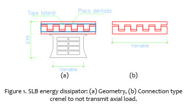
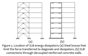
Figure 2 shows the different ways of location of the SLB dissipator. Figure 2 (a) shows the classic application with steel braces that limit the force transferred to the diagonals and dissipators. Figure 2 (b) corresponds to the application through decoupled concrete walls only 15-30 cm thick and with SLB connections. In all these cases the devices do not need to be aligned vertically since the connection does not transfer axial load.
2. Modeling
To numerically characterize the behaviour of SLB dissipators, two types of FRAME or NLINK elements are used. The usual primary analysis with these devices is a spectral modal linear analysis so both elements are correct to start with, although it’s difficult to justify the use of FRAME elements at the moment since the NLINK elements provide similar results and also leave the model prepared for later nonlinear time history analysis.
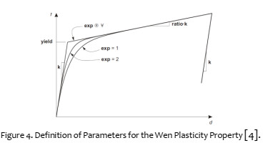
Out of the different types of NLINK offered by programs such as SAP2000 or ETABS, Plastic (Wen) is used, which allows the incorporation of the non-linear properties of the SLB dissipator. The plasticity model used is based on a hysteretic behaviour proposed by Wen. Figure 3 shows the plastic properties of the NLINK element [4].
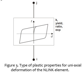
The non-linear force versus displacement relationship is given by the following expression:
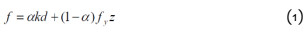
Where k is the elastic constant, f and is the yield force, α is the ratio of post-yielding stiffness and elastic stiffness k, and z is an internal hysteretic variable. This variable has a range between | z | ≤ 1, with the yielding surface represented by | z | = 1. The initial value of z is zero, and it evolves according to the differential equation:
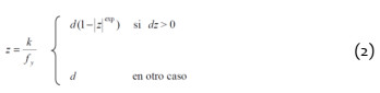
Where exp is an exponent greater than or equal to unity. For the particular case of the SLB dissipator, it is recommended to use an exp value equal to 2.
With regard to the modeling of the structure with uncoupled walls and SLB dissipators, a first aspect is the size of the devices and the length of the support walls. From the top face of the beams and considering that conventional devices measure155mm in length, the support walls could be considered with their initial height (from the top face of the beam) or longer considering the common areas between beams and walls. The closest model is the one shown in Figure 5.
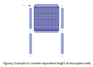
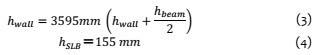
In this case the height of the wall is 3.845m considering the intersection zones on both the upper and lower sides of the wall with the respective beams. Therefore, the heights of the wall and the dissipator are:
In this case the height of the wall in the model is greater than the real one and therefore there will also be a slight increase in its own weight which can be compensated by modifying its density.
Below, the results are presented for different SLB devices analysed by means of a spectral modal analysis with FRAME and NLINK elements to determine the story displacements, the relative displacements between the nodes of each device and their shear. The comparison is in terms of the maximum values in the second level.
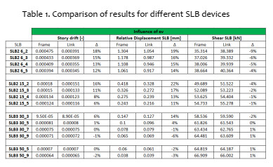
Comparing the last columns, it is observed that the shear level is very similar between both models with differences less than 9% and in general of the order of only 1%. For the story displacements or the relative displacements of each device the difference is greater, but on average less than 10%.
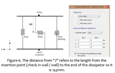
An important parameter in the definition of the NLINK element is the so-called "shear deformation location" or "null moment point". It is defined in ETABS (see Figure 6) as the distance to the inflection point or where the momentum due to the shear on the link is zero BUT MEASURED FROM THE END POINT OF THE LINK. This point on the SLB dissipator corresponds to the crenellated connection where the bending moment is zero and, therefore, this distance is zero or 155mm (depending on how the link is defined or inserted). It is important to keep in mind that automatically loaded devices are defined on local axis 2 and that this distance is defined as zero. Therefore, depending on the crenellated connection, the NLINK must be directed up or down.
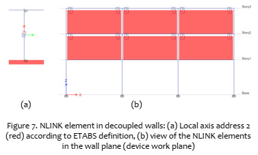
Specifically, in the case of decoupled walls, SLBs are modelled as a link with properties on local axis 2 and their insertion point or "point i" of the NLINK is the upper end of the wall and point "j" is the beam base (where is the crenellated connection or point of moment zero). The "distance from node j" to the point of zero moment would therefore be zero, that is, the local axis "points" or is directed upwards.
On the contrary, for dissipators supported by metallic diagonals (which are normally bi-articulated) the almenada connection is arranged at the junction of the diagonals (and NOT as in the walls at the base of the beam). Since all automatically loaded devices have the null moment distance defined as "zero", their insertion point or point "i" has to be the beam base and the "j point" of the NLINK the end where the diagonals are intercepted (where is the crenellated connection or point of zero moment). The "distance from node j" to the point of zero moment would therefore be zero, which is, in this case the local axis "points" or is directed downwards [4].
For the above and for decoupled walls, work as indicated in the figure below [5]:
In local directions 1 and 3, the displacement of the dissipator could be restricted using the "fixed" sections, but it is recommended to assign a sufficiently low stiffness to limit this displacement (Ex. 10 KN / cm) or better still calculate it according to the connection plates, without affecting the result globally. This recommendation allows the Fast Nonlinear Analysis (FNA) technique to be used using Ritz vectors which significantly reduces computation times. In the directly loaded tables ("plugin") the lateral stiffness was calculated based on the upper connection plates so these values are directly incorporated.
3. ITERATIVE DESIGN METHODOLOGY
This section presents two design methodologies for the automatic selection of SLB power dissipators. These procedures have been implemented in the ETABS program through the DISIPA-SLB plugin [5].
3.1 Direct Design Procedure
This procedure for selecting SLB devices has been automated and implemented in the ETABS program and is always carried out by means of a spectral modal linear analysis that allows a reduced computation time. Schematically, the procedure consists in starting from a group of proposed devices that are updated until the capacity demand of the elastic linear shear obtained by the spectral modal method is less than or equal to 1.5. This value is considered correct by various cumulative factors such as the kinematic hardening of the steel or its greater resistance to dynamic loads, factors that can only be considered by means of a nonlinear time history analysis In this case, a nonlinear time history analysis should still be performed but it is recommended to do so only at the end of the procedure solely for verification.
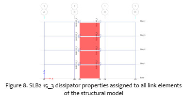
To start the design, the SLB devices must be preloaded to the ETABS model using the Dissipators module of the plugin and, therefore, assign an initial set to all the link elements previously defined in the structural model. In this case, the SLB2 15_3 type with its properties defined in the ETABS model is chosen.
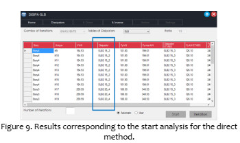
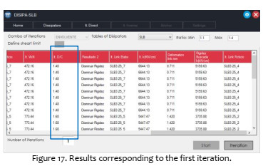
After assigning the typical property to the links you must choose the combination of iteration and then execute the "start" button to start the design of the devices. For the example below, the "ENVELOPE" was chosen as an iteration combination and as a result of the initial analysis the new properties for the links in the "dissipator" column of the plugin table are obtained.
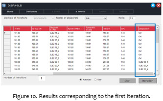
To assign the new properties obtained in the first analysis to the links, the "iteration" button of the plugin is executed and it will automatically change the properties of the links in the ETABS model and then analyse the model and verify that the D / C is less than 1.5. In this example, in the results of the first iteration, only the devices of the fourth level have a D / C of less than 1.5, so they obtain an "Ok" in the "Dissipator I" column of the plugin and for the devices from the first to the third level the new properties for the links are obtained.
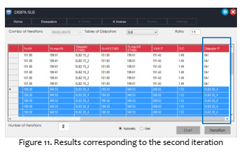
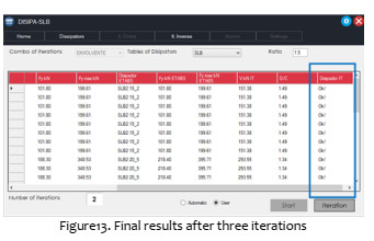
To proceed to the second iteration, the "iteration" button must be executed again and it will assign the properties obtained in the first iteration. For the example values obtained in the second iteration, the links of the second and third floor have a D / C close to 1.5 and the recommended property is the same as the model, which means that the automatic iteration has ended because the following iteration would obtain the same results.
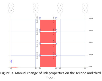
To make the system converge in its entirety, you must activate the user mode of the application and make the manual change of the ownership of the link with another with greater resistance to which it has been assigned and re-iterate to verify the D / C. Therefore, the dissipator that follows in resistance to the one assigned to it must be assigned in the model. For example, in Axis A, story 3 the SLB2 20_4 dissipator is assigned, and the iteration indicates the same dissipator, so the SLB2 20_5 dissipator will be chosen. Similarly, in story 2, the SLB3 25_3 dissipator is assigned, and in the iteration indicates the same result, so the SLB3 25_4 dissipator will be assigned to the model.
After assigning the properties manually to the links, the iteration is executed again with the application in the user mode to verify the new D / C. In the user iteration, values below 1.5 are obtained in all links, so the design by the direct method is finished.
In this example, only 2 automatic iterations and one user iteration were necessary to reach the final design of the devices.
3.2 Inverse Iterative Design Procedure
The "fixed force" or "reverse" iterative procedure is an alternative to the "direct iteration" procedure to limit the thicknesses of the decoupled walls and size of the devices since said "direct" procedure consecutively increases its dimensions. Thicknesses of decoupled walls greater than 300 mm are usually excessive due to architecture and cost, just as the buckling of metal diagonals can be a condition for fixing a "maximum force." According to the ACI, the cutting capacity of a structural wall (obtained considering a certain value of f'c, length and thickness) is fixed, and, according to this capacity, is the value of the maximum force that could act on the devices. Unlike the direct iteration procedure, which usually increases the size of the dissipator at each iteration, as well as its shear force, in the iterative "reverse" procedure, the value of the shear force in the dissipator is set and, therefore, the iteration consists in reducing the size of the device in the numerical model (and not in reality) in order to calibrate such transferred shear force.
The selection procedure of the SLB devices is always carried out by means of a spectral modal linear analysis that allows a reduced computation time and therefore, as for the direct iteration; a D / C limit is established. Next, a step-by-step example is developed using the DISIPA-SLB plugin.
To start the design, SLB devices must be preloaded to the ETABS model using the Dissipators module of the plugin.
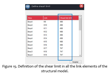
To execute this method, it is first necessary to limit the shear of each link to the maximum resistant shear of the element that will support them, and from that value the devices set that will be used in the first analysis is chosen. In this example the devices were located on uncoupled walls and at both ends of them, so that the maximum shear in the link is given by half of the maximum shear force of the wall.
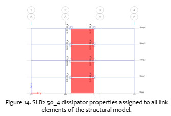
Once the shear limit is assigned, the iteration combination is chosen and then the Start button is executed. For the example, the property SLB3 50_4 was assigned to all links in the model and the combination "ENVELOPE" was chosen as the combination of iteration. As a result of the initial analysis, a column of fictitious devices was obtained in the plugin, which will replace the property of each link that has a D / C outside the range of 1.1 and 1.4.
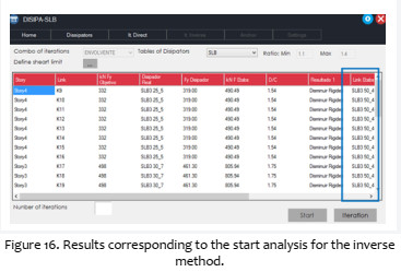
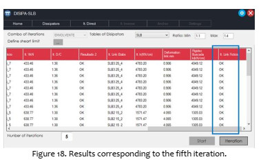
To assign the properties obtained in the first analysis to the links, the "iteration" button of the plugin is executed and it will automatically change the properties of the links in the ETABS model and then analyse the model and verify the D / C. In this case the D / C values of the first iteration are higher than 1.48 which is above the acceptable range and it is necessary to continue iterating.
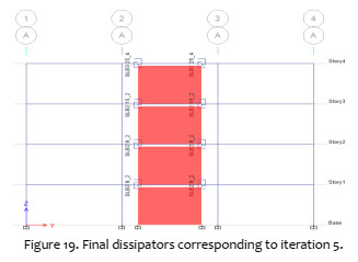
The iterations must be repeated until a ratio value is reached within the design range of 1.1 and 1.4. In this example, 5 automatic iterations were necessary to finalize the design. The D / C range is considered to be the strictest in this procedure to direct iteration for greater safety in the final result that must always be verified with a non-linear TH procedure which, when using NLINK elements, the ETABS model is ready for execution.
4. NONLINEAR TIME HISTORY ANALYSIS
The dynamic nonlinear analyses were carried out in order to verify the contribution of SLB dissipators to a structure denominated the SLB Building.
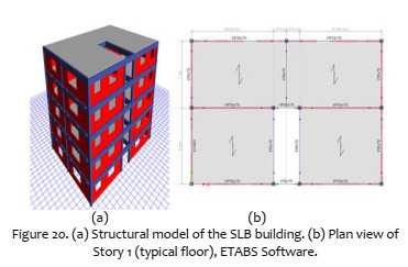
The SLB building corresponds to a precast building, regular in plan and elevation, for residential use located in an area of high seismicity in Peru. The proposed architectural project concerns infrastructure of five levels with a total height of 15.5m, as shown in figures 20 (a) and 20 (b). It has 4 apartments per level and rooftop. The objective is to design a safe, economical, functional and innovative structure in accordance with seismic standards, in addition to promoting the use of precast materials in favour of the industrialization of construction in the region [6]. The base structural proposal consists in a model equipped with devices of seismic protection, type Shear Link Bozzo (SLB). The resistant system is defined by square columns of 40cmx40cm, beams of 35cmx70m (of lengths greater than7 meters), precast unidirectional pre-slabs of 35cm and uncoupled concrete walls of 12cm. (Fig 20b).
The vertical loads are assigned to beams, columns and pre-slabs, while the seismic actions are transferred to the system composed of uncoupled walls and SLB dissipators. All the beams have been modelled as bi-articulated to mainly absorb vertical loads that generate bending moments and shear forces. Regarding the connection at the base of their 11 columns, it has been considered appropriate to evaluate two cases: fixed and hinged.
4.1. Nonlinear Analysis Time History
The nonlinear step by step analysis in time using 10 preselected seismic signals (compatible with Peruvian Spectra in S1 soil condition in Zone 4) applied in two horizontal directions and according to current code. The SLB devices are predefined to satisfy the requirements of normative displacements between storeys, and then the columns have been designed. The structural calculations and modeling of the building have been made using the ETABS Software with ability to evaluate the non-linearity of SLB devices that have been located between decoupled walls and beams. The model has 120 devices (24 per level).
4.2. Result processing
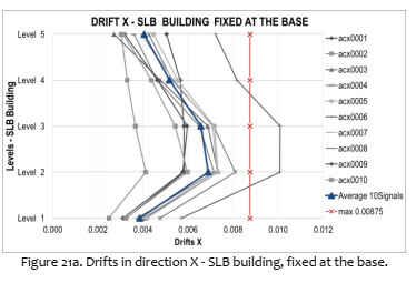
As part of the post-processing of the results obtained, the drifts are presented in the x and y directions of the fixed and hinged SLB Building at the base, in the same way, the maximum accelerations per storeys for each seismic signal.
The following figures show the distortions and accelerations of the structure for each seismic signal and for each level. The figures 21a and 21b show the average drifts of the 10 signals used for the columns fixed in the base with average values between 0.0038 and 0.0070. We can see that the maximum drifts are in the second level and all values are lower than the maximum limit of Peruvian Code, which for this type of analysis is 0.00875.

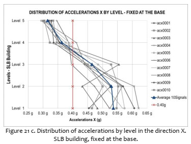
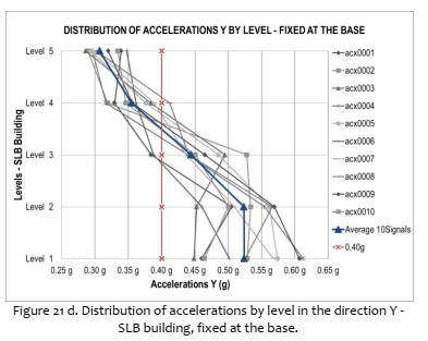
The figures 21c and 21d show the floor accelerations of the SLB Building when the columns are fixed in their base. The accelerations are greater in the lower floors, and their average values are between 0.32g and 0.55g in both directions.
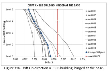
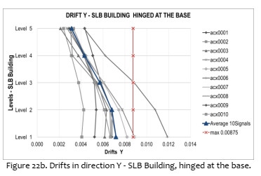
In the same way, when changing the connection at the base of the columns to a hinged system, schematic results are obtained in Figures 22a and 22b, where the major inter-story drifts occur at the first level (for each signal). Their average values are in the range of 0.0027 and 0.0073. These values are similar to the building with columns fixed at the base.
In the case of accelerations per level for the hinged building at the base, they tend to behave analogously to the case of the fixed building, although with slightly lower values with average values between 0.30g and 0.50g in both directions (Figure 22c and 22d).
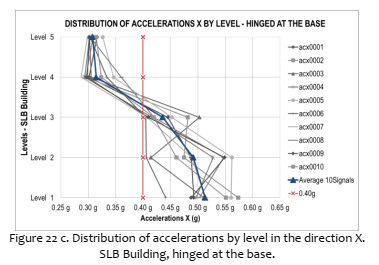
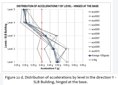
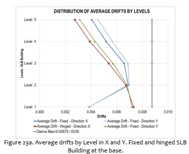
In Figures 23a and 23b, the drift averages and the distribution of absolute accelerations in each level, respectively, for SLB buildings with the base of the fixed and hinged columns are schematized. It can be inferred that, for the selected devices and in both cases, the drifts are below the maximum allowed. On the other hand, there is the same reduction of accelerations in the last levels with respect to the lower ones (in both directions).

Finally, the Figure 24 shows the values of the seismic coefficients C, which relate the basal seismic force and the seismic weight of the structure, for each of the ten signals used. It can be observed that in the case of the hinged structural system, values between 0.128 and 0.185 are obtained; while if it were fixed structure, the results would be bigger.
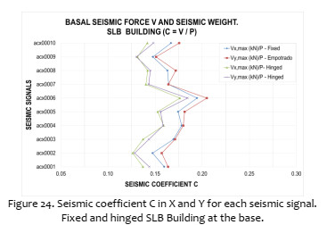
It is concluded that, apparently the hinge model at the base would be a better option with respect to fixed support, as shown in the previous graphs. However, it should be noted that both types of connections satisfy the normative seismic requirements.
CONCLUSIONS
The SLB energy dissipators for seismic protection provide 52+52 standard devices that, combined in parallel with one another, result in a very large potential set. The unit cost of these dissipators is very cheap with the objective of using them massively in order to significantly affect structural response. This advantage has the drawback that each set of devices selected provides different structural performance levels resulting in analysis/design complexity. Larger devices may result in less structural damaged controlled by inter-story drift but increasing their cost and story accelerations. Consequently, it is convenient to automate as much as possible the selection process in order to optimize global structural response taking into account usual strict architectonic limitations in their position or theirs supports elements.
This article initially compares FRAME and NLINK elements in order to model the SLB devices. It is concluded that the precision level is similar but the NLINK approach has the advantage of providing a model ready for the nonlinear analysis. Consequently, an application that automatically loads all the standard simple and combined SLB devices modelled as NLINK elements has been developed and implement in the ETABS program. Using this database, two iterative procedures were implemented in a plug-in. This application allows automatic selection of a given set of device locations based on architectonic restrictions. In order to efficiently complete the analysis, the procedures are linear elastic using the modal spectral analysis method. A subsequent nonlinear time history analysis for the selected set of devices may allow final verification. The two automatic selection procedures are: (1) direct iterative and (2) inverse iteration or fixed force procedure. In the first one, given a supposed set of devices, the application iterates forward according to the linear shear force determined for each device.
Starting for an "n" iteration the obtained shear force for each set of devices is compared to the initial yielding force for the corresponding device and a Demand/Capacity (D/C) ratio is determined. Consequently, if the D/C is larger than a fixed value the "n+1" iteration determines the new devices according to the device shear force. For the direct procedure the D/C ratio is fixed to 1,5 taking into account kinematic hardening in the hysteretic loops as well as over strength due to fast dynamic loadings, among other factors. In the second procedure the force is fixed based on the maximum capacity of the supporting uncoupled concrete walls or the buckling force of the supporting steel braces. The procedure iterates in order to obtain a fictitious set of devices in the ETAB model such that the objective fixed force is achieved also with a D/C ration. In this case the D/C ratio is set between 1.1 to 1.4 in order to not overestimate the shear force transferred by the devices (which ends up reducing the story force for the structure).
Finally, the article includes a 5-story precast building incorporating 120 SLB simple devices. The building has hinged beams and full seismic protection is achieved using these devices. The building is precast in order to provide a potential solution for low income families around Peru. There are 4 departments per each level without interior columns or walls that the user may accommodate to their convenience. The analysis performed is nonlinear time history based on 10 signals compatible with the Peruvian spectra for R=1 in a S1 soil condition in Zone 4. Two structural configurations were studied for the 11 columns that include the SLB building: (1) fixed or (2) hinged at their bases. In the second option and without the uncoupled walls and devices the system would be unstable but clearly this is not the case with the walls and dissipators. The performance of both solutions is compared and in terms of drifts the results are similar between 0.003 and 0.007 all smaller than the 0.00875limitation of the Peruvian code for this type of analysis. In terms of floors accelerations, the range is between only 0.3g to 0.5g with smaller values for the hinged column base solution and in all cases with a clearly reduction with height achieved by the energy dissipated by the devices. Taking into account that for the selected spectra the seismic coefficient is around 1.2g a clear isolation is achieved particularly for top stories with a ratio of 4 (1.2g/0.3g). Similar conclusions are obtained for the story shear forces divided by the structural weight with values around only 0.12 and 0.20 for the 10 earthquake signals. This result implies an "R" reduction factor between 6 and 10 for the SLB building without any structural damage since 100% of the input energy is dissipated by the devices. At the same time the solution achieves low displacement levels compatible with immediate occupancy. Finally, this solution is only comparable in safety and quality to base isolation but with the significant advantages of its simplicity, low cost and minimum or no special maintenance required using affordable and Peruvian technology.
REFERENCES
[1] Franchioni G 2001 Experimental investigations on semi-active and passive systems for seismic risk mitigation, ISMES Report No. 7. [ Links ]
[2] Cahis X, Bozzo L y Torres LL 1998 Experimental studies of various innovative energy dissipation devices, Proceedings of the Eleventh European Conference on Earthquake Engineering, Paris [ Links ]
[3] Bozzo L, Barbat AH 1999 Diseño sismorresistente de edificios. Técnicas convencionales y avanzadas. Barcelona: Editorial Reverte. [ Links ]
[4] CSI2015 ETABS Manual. Computers and Structures, Inc., Berkeley, CA. [ Links ]
[5] Bozzo L, et al.2019 Manual de procedimiento para el diseño con SLB (in Spanish). [ Links ]
[6] Nuzzo I, Losanno D, Serino G, and Bozzo L 2015 A Seismic-resistant Precast r.c. System equipped with Shear Link Dissipators for Residential Buildings, International Journal of Civil and Structural Engineering, IJCSE Vol. 2:Issue 1. [ Links ]
1 Corresponding author:
Received: 25/07/2019
Accepted: 12/08/2019

