


Servicios Personalizados
Revista

Articulo
 Inglés (pdf)
 Articulo en XML
 Referencias del artículo
 Enviar articulo por email
Indicadores
-
 Citado por SciELO
Links relacionados
-
 Similares en
SciELO
Similares en
SciELO
Compartir

 Permalink
Tecnia
versión impresa ISSN 0375-7765versión On-line ISSN 2309-0413
Tecnia vol.29 no.2 Lima jul. 2019
http://dx.doi.org/10.21754/tecnia.v29i2.714
10.21754/tecnia.v29i2.714
EARTHQUAKE ENGINEERING DESIGN AND EVALUATION
Damage mitigation and retrofit of non-structural components on buildings subjected to blast loading
David Holgado, P.E. 1*
1 Stone Security Engineering, San Antonio, TX; USA
ABSTRACT
Structures in chemical and petrochemical facilities are often located in areas that may be subjected to blast loading. Occupied buildings typically have non-structural components located along the interior of the exterior walls and roof such as windows, doors, wall mounted AC units, lights, furniture, storage racks, hanging equipment, and loose articles. Occupants of buildings subjected to accidental explosions may be injured from glass fragments and interior non-structural items becoming projectiles and impacting building occupants. As a pressure wave from a blast impacts the exterior of a building, the wall and roof components are rapidly accelerated inward. Equipment or contents mounted on or in contact with the exterior façade are also accelerated and may be dislodged and projected as debris. Items anchored to the ceiling structure can be thrown vertically from the initial forward deflection of the supporting member or break free from their supports and become falling debris hazards. Therefore, evaluation and mitigation of non-structural debris for buildings subjected to blast load is important to further mitigate the potential hazards to personnel occupying these buildings. This paper provides design retrofit recommendations based on accident investigation experience at chemical and refining facilities and engineered solutions for typical hazards commonly observed at these facilities.
Keywords: blast load, explosion, risk mitigation, reliable design, non-structure.
1 INTRODUCTION
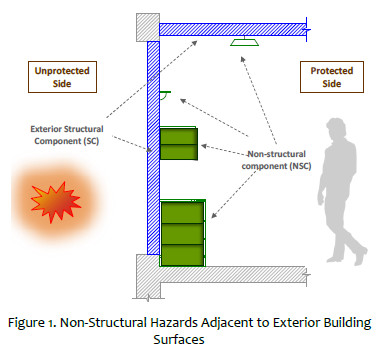
In blast related events, injuries may result from glazing fragment hazards and interior articles that become projectiles and impact building occupants. Hazards associated with non-structural components occur when the pressure wave from an explosion impacts the exterior surfaces of a building. The wall and roof structural components and the attached interior components are rapidly accelerated inward. After reaching peak inward displacement the structural members spring back, creating a dynamically applied reaction force on the connection between the structural components (SC) and non-structural components (NSC). Connections that are too weak to resist these reactions break free from the loaded surfaces and the NSC are propelled into the occupied spaces of the building.
Non-structural hazards result from items of notable weight attached to or in contact with exterior walls or ceiling. Common examples of these items are bookcases, filing cabinets, storage racks, wall mounted fixtures, overhead lights and air conditioning diffusers. As a general rule most items mounted overhead or located 48-inches or higher above the floor, can pose a hazard to occupants in the event of an accidental explosion.
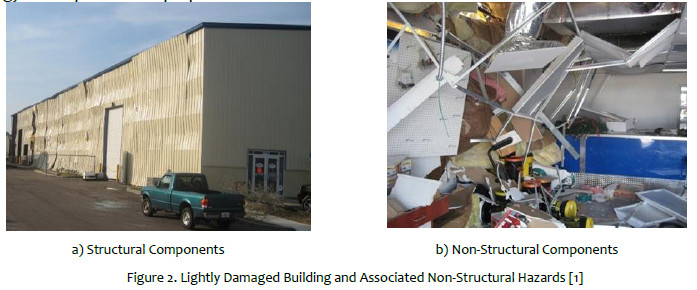
Figure 1 depicts a typical vertical cross-section of a building with non-structural components secured to exterior structural components. An example of the non-structural hazards that can result even at lower building damage levels is provided below in Figure 2
The response of non-structural components (NSC) to blast loading is associated with the response of the attached structural component (SC) in order to determine the design basis acceleration for supporting
Note that the upgrade solutions developed in this paper are not intended to prevent damage to the fixture itself (i.e. internal/external mechanical or electronic damage) but rather to mitigate the hazards to occupants. Also, window glazing and door response to blast loads are not included but can also present non-structural hazards. They should be addressed on a case by case basis for each building.
2 DESIGN METHODOLOGY
2.1 Structural Response Prediction
Structural components subjected to blast loading are commonly analyzed utilizing the Single Degree of Freedom (SDOF) method [2] . The SDOF solution is obtained using simple numerical integration methods and the Single-Degree-of-Freedom Blast Effects Design Spreadsheet SBEDS [3] is one of the publicly available tools.
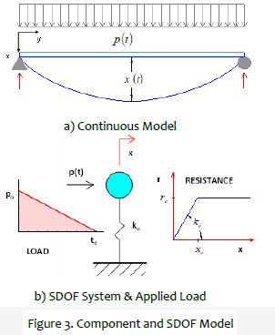
Closed form solutions of the SDOF response are difficult to obtain because of material non-linearity and variation of loading. However, an analytical solution of the SDOF response has been achieved considering certain assumptions and simplifications as described in the following sections. The typical representation of SDOF system is depicted in Figure 3.
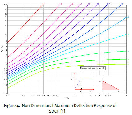
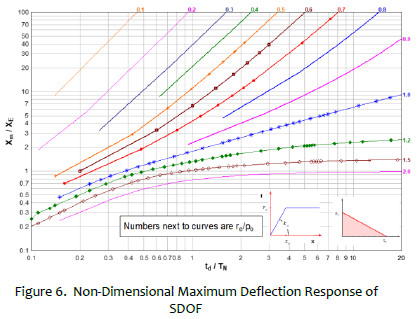
Although the peak deflection of SDOF elasto-plastic system could be predicted using simplified charts, such as the one shown in Figure 4, [2] , the charts predicting the acceleration at the moment of maximum deflection, which is the design basis acceleration for restraining the non-structural fixture, are not available.
2.2 Assumptions and Approximations
Mass is uniformly distributed along the span of the component.
The assumed shape function, , is applicable for deflection, velocity and acceleration. )(y
The applied blast load is assumed to be right triangular with an instantaneous rise to peak pressure, po, and a linear decay to ambient as illustrated Figure 3 b).
The resistance function follows a bi-linear configuration as shown in Figure 3 b).
The component has adequate shear strength to transfer the reaction forces during the component response.
For components having resistance other than bilinear due to support constraints (e.g. Fixed-Simple, Fixed-Fixed, etc.), the approach described herein is still applicable. The equivalent elastic stiffness, kEQ, should be computed that results in the resistance deflection function having equal strain energy.
2.3 Component Response Prediction
2.3.1 Deflection Response Prediction
The analytical solution is implemented in Visual Basic code and the SC ductility is plotted for the SDOF system as a function of the ratio of the duration of the blast load to the natural period (td/Tn) and the dynamic load factor (re/po) = [0.1, 0.2.. 1.5, 2.0] and then, the non-dimensional plot is generated as shown in ¡Error! No se encuentra el origen de la referencia.. The computed solution in ¡Error! No se encuentra el origen de la referencia. is identical to plots provided for simple SDOF solutions as shown previously in ¡Error! No se encuentra el origen de la referencia..
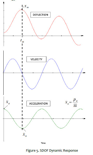
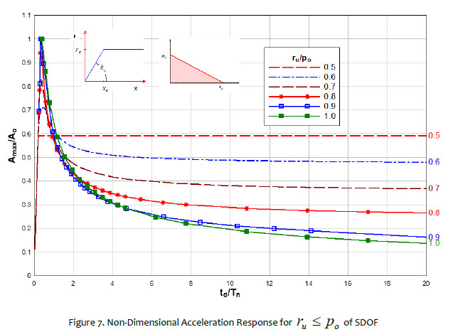
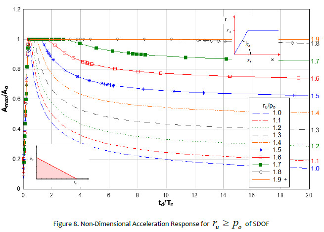
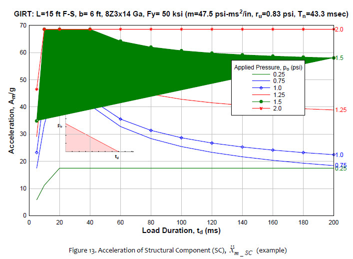
2.3.2 Acceleration Response Prediction
In a manner similar to the prediction of peak deflection described in previous section, the design basis acceleration (occurring at the time when the maximum deflection of the SC is achieved) is plotted also as a function of ratio of the load duration to the natural period (td/Tn) and the dynamic load factor (re/po) for ru ≤ po and ru ≥ po as shown in ¡Error! No se encuentra el origen de la referencia. & ¡Error! No se encuentra el origen de la referencia., respectively. ¡Error! No se encuentra el origen de la referencia. & ¡Error! No se encuentra el origen de la referencia. may be utilized to determine the design basis acceleration for retrofitting the non-structural fixture attachment to the supporting SC.
3 RETROFIT DESIGN TECHNIQUES
3.1 Assumptions and Limitations
-
Structural components should be limited to Medium Response or lower as defined in Appendix 5.B of ASCE ¡Error! No se encuentra el origen de la referencia.; this component response allows certain permanent deformation during blast loading but it is still repairable.
-
The building must be designed and constructed according to modern conventional construction practices, within the last 50 years using wood, steel, masonry or concrete. This excludes temporary buildings or trailers.
-
The mass of the fixture is insignificant compared with the mass of the structural component and the fixture behaves as a rigid body during dynamic response of the structural component. In other words, there is no interaction effect during the response of the structural component and non-structural fixture as computed using the corresponding SDOF approach.
-
The fixture is located near the location of the maximum response of the structural component (i.e. midspan).
-
The fixture is in contact with the structural component prior blast loading (i.e. no impact effect).
-
The fixture is not attached to cladding but is attached to a secondary framing component (e.g. purlin, girt, joist, etc.) or primary framing component (e.g. column, beam, Concrete Masonry (CMU) wall, etc.).
-
The connection between the fixture and structural component is assumed to be rigid.
-
The upgrade solutions developed herein are not intended to prevent damage to the fixture itself (i.e. internal/external mechanical or electronic damage) but rather to mitigate the hazards to occupants.
-
Window glazing and door response to blast loads are not included but can also present non-structural hazards. They should be addressed on a case by case basis for each building
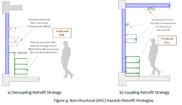
3.2 Decoupling Retrofit Strategy
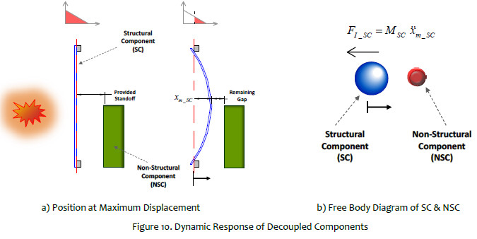
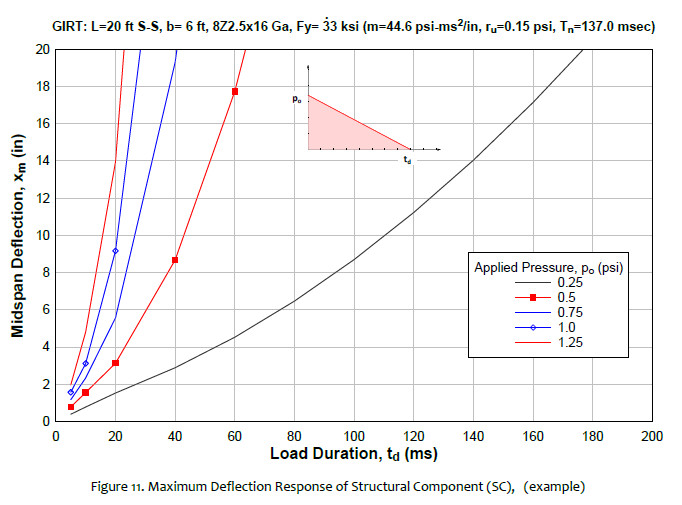
Of the two retrofit options, decoupling is the simpler one to implement. This technique is based on the concept of providing sufficient distance for all heavy fixtures from the exterior building surfaces (i.e. walls and roofs), as shown in ¡Error! No se encuentra el origen de la referencia. a). A safe offset is computed based on the maximum inward displacement of the structural component along the exterior surface as shown in ¡Error! No se encuentra el origen de la referencia.. Thus, the maximum displacement of the primary or secondary framing system is computed for the applied blast load. ¡Error! No se encuentra el origen de la referencia. depicts an example of maximum deflection of component under a set of applied blast loads. The non-structural fixture is then separated from the structure by sufficient distance to accommodate the total deflection of the supporting SC.
3.3 Coupling Retrofit Strategy
Since the decoupling retrofit technique is based on providing sufficient standoff distance between fixtures and loaded exterior surfaces, the availability of sufficient room is critical and in many cases that may not be a feasible retrofit option. In those instances, the coupling retrofit technique will need to be evaluated for implementation. Figure 9 b) depicts the general concept of the coupling option retrofit.
As the coupling retrofit relies on the fasteners between the SC and the non-structural fixture it is imperative the connection be sufficient to withstand the imparted forces at the time of peak displacement and the onset of structural rebound. The forces used to develop the connection requirements are based on the mass of the fixture and the acceleration of the wall at the point of maximum inward displacement, as depicted in Figure 12. Several assumptions are made in order to compute the acceleration of the fixture which are described in Section 2.3.2.
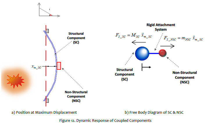
Figure 13 depicts an example of design basis acceleration of component under a set of applied blast loads
3.3.1 Computation of Required Anchorage Forces
The required anchorage forces on NSC are based on the predicted acceleration of the structural response (at maximum displacement), as described in Section ¡Error! No se encuentra el origen de la referencia., and the mass of the attached fixture. ¡Error! No se encuentra el origen de la referencia. shows in example of peak acceleration of components per type of building construction.
Some common NSC to be retrofitted are identified including their corresponding weight as shown in ¡Error! No se encuentra el origen de la referencia..
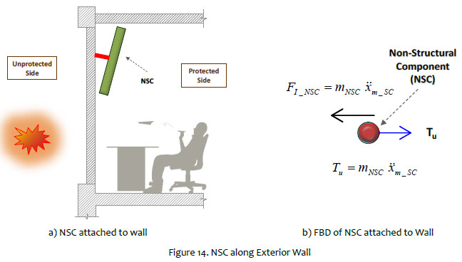
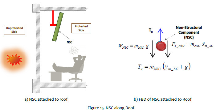
In addition to the loading from the blast, gravity loads are imposed on non-structural components affixed to the roof. However, this refinement may be meaningful only for certain components. Using as example the values from ¡Error! No se encuentra el origen de la referencia., the gravity effect on wood components may increase the anchorage force by 20%. For the other roof components (i.e. steel purlins, Open Web Steel Joists, (OWSJ)), the gravity effect could be disregarded. ¡Error! No se encuentra el origen de la referencia. and ¡Error! No se encuentra el origen de la referencia. depict the free body diagrams (FBD) of anchorage forces along wall and roof surfaces, respectively.
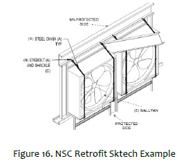
Finally, the strength of the provided anchorage used to restrain the NSC must be greater than the required force as shown in ¡Error! No se encuentra el origen de la referencia.. Also, this retrofit technique may require the connection between the fixture and structural component formed by several pieces of hardware rather than single fasteners (i.e. hooks, chains, straps, etc.). Therefore, all hardware involved in the connection must comply with the required strength through the load path. As an example, ¡Error! No se encuentra el origen de la referencia. depicts the retrofit of wall fans mounted on exterior wall.
RECOMMENDATIONS
In addition to the anchorage requirements for the coupling retrofit technique described in the Section¡Error! No se encuentra el origen de la referencia., some wall/roof conditions may require special attention as follows:
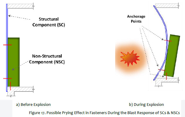
- Placement of anchorage in location that does not induce prying in fasteners; see ¡Error! No se encuentra el origen de la referencia..
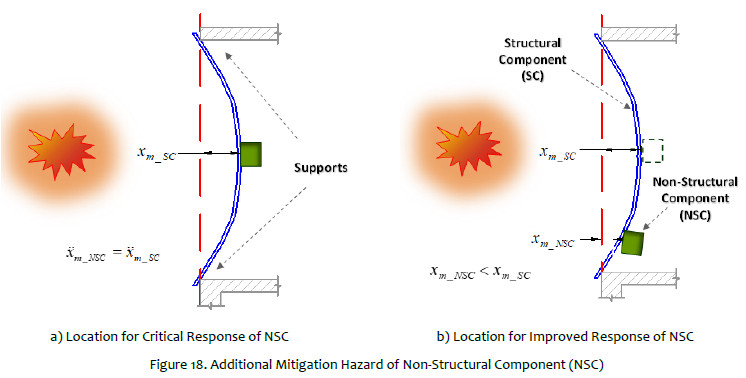
- Placing the NSC near the support of the structural component and away from the point of peak deflection may significantly reduce the anchorage requirements; see ¡Error! No se encuentra el origen de la referencia..
- NSCs that are relatively large compared with the structural component length may reduce the anchorage requirements because acceleration of fixture varies along its length; see ¡Error! No se encuentra el origen de la referencia..
- Anchorage for retrofit must be installed into secondary or main frame members capable of supporting the design basis forces.
CONCLUSIONS
Evaluation of non-structural building components for the potential to become hazardous debris and mitigation of predicted hazards for buildings subjected to blast load is important to mitigate the hazards to personnel occupying these buildings. A methodology for creating simplified design tool for addressing these hazards was presented and two approaches for retrofitting non-structural components by separating the component from the building structure or by determining the required forces to attach the fixture to the structure were also provided and illustrated.
ACKNOWLEDGEMENT
Author would like to deeply thanks ABSG Consulting for providing some references as well as Ben Harrison III for reviewing this paper.
REFERENCES
[1] Ben Harrison, Sanaa Alaoui, "T2 Laboratories Explosion Damage Assessment", 34th DDESB Explosives Safety Seminar (2010). [ Links ]
[2] Biggs, J.D., "Introduction to Structural Dynamics," McGraw-Hill Publishing Company, New York, NY, (1964) [ Links ]
[3] "Single-degree-of-freedom Blast Effects Design Spreadsheets (SBEDS)", PDC-TR 06-01 Rev 3, U.S. Army Corps of Engineers Protective Design Center, December 2014 [ Links ]
[4] Unified Facilities Criteria (UFC) UFC 3-340-02, Structures to Resist the Effects of Accidental Explosions, September 2014 [ Links ]
[5] ASCE Task Committee on Blast-Resistant Design. "Design of Blast-Resistant Buildings in Petrochemical Facilities" 2nd. Edition (2010) [ Links ]
* Corresponding author:
david@stonesecurityengineering.com
Received: 18/07/2019
Accepted: 12/08/2019

