


Servicios Personalizados
Revista

Articulo
 Inglés (pdf)
 Articulo en XML
 Referencias del artículo
 Enviar articulo por email
Indicadores
-
 Citado por SciELO
Links relacionados
-
 Similares en
SciELO
Similares en
SciELO
Compartir

 Permalink
Tecnia
versión impresa ISSN 0375-7765versión On-line ISSN 2309-0413
Tecnia vol.29 no.2 Lima jul. 2019
http://dx.doi.org/10.21754/tecnia.v29i2.722
10.21754/tecnia.v29i2.722
EARTHQUAKE ENGINEERING DESIGN AND EVALUATION
Seismic structural assessment of a 40 years old melt shop facility
Guillermo Huaco1*, Waldo Inga 1, Audry Camacho2
1 Civil Engineering Faculty, National University of Engineering, Lima, Peru.
2 HATCH PERU, Lima, Peru.
ABSTRACT
Assessment of old factory infrastructure is required in order to keep them working especially after natural hazard event such as earthquake, tornados, or variation of gravity loads. This type of structure is considered essential since it should be safety for workers during operation time and to avoid possible economical losses if this facility stops its operations after any main seismic event. It is presented the structural assessment of the infrastructure of a melt shop facility, which it used for production of structural steel shapes. This infrastructure was built at the beginning of 80s and it is located at near Pisco city in Peru. Reinforced concrete C columns and L beams make the frames of the structure and the rood is made by steel trusts. NDT and destructive tests were made for the reinforced concrete members as well of extraction of steel coupons from the roof trusts. Auscultation of foundation, reinforced concrete and steel structures were performed. It was found that several columns present damages such as spalling of cover, impact hits from heavy vehicles, which get in the interior of the facility. The roof presents metallic dust which was accumulated by the smelter operation. Heat of 50 Celsius degrees is the average temperature during the 20hours per day of operation time. Besides, capacity of several reinforced concrete columns and beams, and steel members of the roof is minor that their demands respectively according to Peru and international codes. The performance of the full structure of the melt shop including concrete and steel structures presents allowed drifts according seismic provisions, however this structure behaves on its nonlinear range under demands of Peru seismic code.
Keywords: Melt Shop, performance base design, bridge cranes.
1. INTRODUCTION
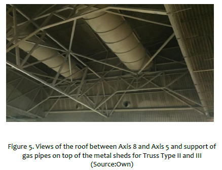
The melt shop facility is located These trusses are 30m length, which receive the load of heavy pipe systems for extraction of gas from the melt of steel area at the interior of the facility.at district of Pisco, department of Ica in Peru and it began to operate 40 years ago. The structure consists of reinforced concrete frames and steel roof, which it is used to the melt metal in order to make new structural steel shapes. It has a total area of 5000 m2 having a width is 45m and length 111m. The structure consists of a reinforced concrete frames with C shapes of Columns of 26m height and L shapes of beams of 14m length which carries 3 cranes of 10t, 80t and 130t lifting weight. The roof is made by 3 different types of steel trusses. These trusses are 30m length, which receive the load of heavy pipe systems for extraction of gas from the melt of steel area at the interior of the facility. As well the roof carries the load from gangways for maintenance operations, as well wind pressure since the melt shop is located at high wind speed zone accords Peruvian wind velocity maps. This facility is on operation time 20 hours per day.
Since the capacity of the ovens was increased, and a new crane with a load capacity greater than the existing ones was installed due a plan of extension for production, the structure was reinforced at 2006. At that time, it was assumed that the quality of the existing concrete as the same as indicated in the original drawings; however, quality of material of this infrastructure has degradation due high temperatures of the melt oven besides impact and moving loads from the crane.
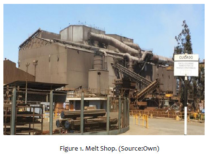
Due these circumstances, the owner of this facility commissioned the structural seismic evaluation to the consultant-engineering firm HATCH in order to assess the capacity of the current concrete and steel structure of the current and steel structurefor current loads due new extension and application of new loads. Figure 1 shows the current view of the meltshop.
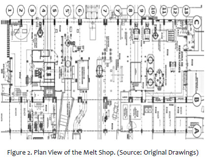
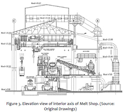
The structure has 15 transversal axes and 3 longitudinal ones as Figure 2 shows. Distance between transversal axes is 7.5m and the larger one is 14m from Axis 6 to 7. Length between Axis B to C is 30m and between A to B is 15m. The cranes of 130t runs from Axis 1 to Axis 8 and the crane of 80t runs from Axis 8 to 13, both cranes are supported onto Axis B and C on L beams. The crane of 10t runs between Axis 1 to 13 and it is supported at Axis A and B. Figure 3 shows an elevation view where location of cranes can be seen, also height of each level.
The current conditions of concrete and steel members work were screened on field. The high temperatures and large amounts of dust accumulated on the roofs make the steel structures the most affected. The concrete structures in general are in good condition, except for some exterior columns that have the exposed reinforcement steel for which immediate repair is recommended. In addition, the roof structure needs periodic maintenance to avoid dust accumulation and anticorrosive paint detachment.
Two test methods were performed for concrete strength: Non Destructive Test NDT using sclerometer and destructive one with extraction of cores. Bothe methods were applied in order to confirm the values fc values with both methodologies since there were many doubts regarding the quality of the concrete around all the body of depth beams and large dimensions of columns. From these tests, the minimum and maximum f'c compression capacity of 239kg/cm2 and 328kg/cm2 for columns, 234kg/cm2 and 269kg/cm2 for beams and foundations of 302kg/cm2 and 343kg/cm2 were measured according to provisions of ASTM C42 [1]. NTD performed to corroborate the result of the concrete specimens confirm the quality of the material following the ASTM C805 [2]. According to the original plans sent by the owner of the facility, indicate that values of fc were 280kg/cm2 for beams and columns, and 210kg/cm2 for foundations. Strength of concrete tends to harden over time and thus increase its capacity to compression, however, given the particular environmental conditions under high temperature, this hardening is not observed at every measured member.
Regarding the conditions of the roof structure, the results obtained from the tests on 3 steel coupons show that its properties have been maintained over time even in the elements that are on the furnace. Original drawing indicated specification for strength of structural steel, therefore the roof steel material would have 46.00kips/in2 and 58.00kips/in2 of yielding and rupture capacity respectively according to AISC Steel Construction Manual [3] for these type of shapes. Because this uncertainty the tests were performed and it was obtained 44.81kips/in2 yielding and 61.80kips/in2 in rupture, tests performed according to ASTM A1067 [4]. These results show that the temperature of the environment has not degraded much the quality of the material.
The support of the steel trusses of the roof conditions varied compared to original drawings provided by the owner. Beside, verifications of steel shapes dimensions were also made, besides the large and heights of members. The roof structure is not observed with lack of maintenance, there are dents and metal dust accumulation in the members trusts, as well as anticorrosive protection painted debonded at several areas.
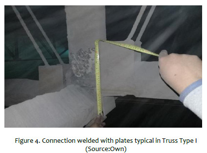
The connections of the Truss Type I are made by gusset plates and angular shapes. These are wrapped in metallic dust as can be seen in Figure 4 and the layer of paint on top of the surface, angles shapes, connections and plates; they are detached.
For the connections of the Truss Type II and III formed by square and rectangular hollow shapes, the connection is welded all around. There is metallic dust which is accumulated on the surface of the steel shapes. See Figure 5
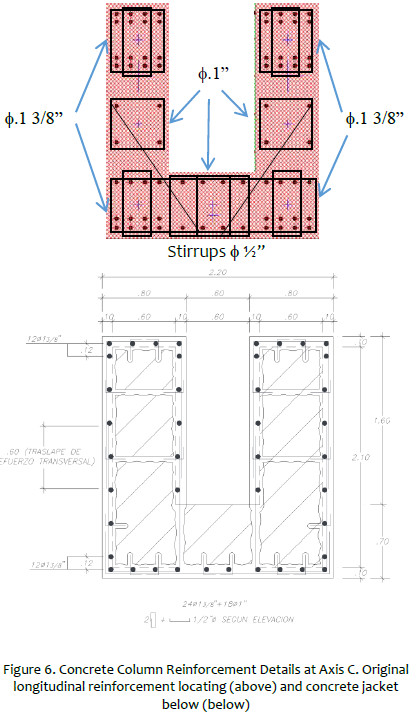
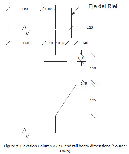
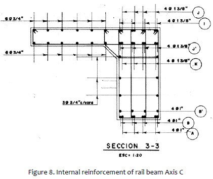
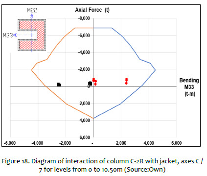
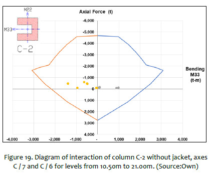
Drawings made for the original construction were provided by the owner. It can be seeing C-shape columns of 60cm thickness and 2.10m x 2.40m base and deep section, as it can be seen in Figure 6, also the longitudinal and transversal reinforcement. Columns at Axis C and B between Axis 6 to 9 presents concrete jackets and the rest is original condition. Besides, dimensions of rail beams for the heaviest cranes are shown in Figure 7 and reinforcement in Figure 8.
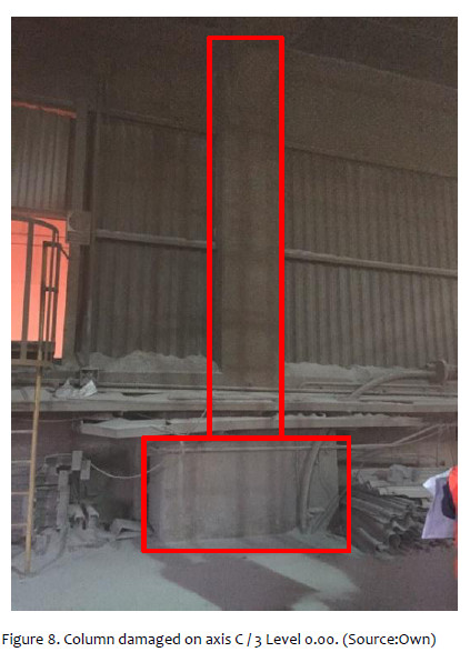
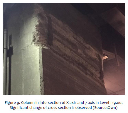
During auscultation of the reinforced concrete frames, the measurements of the original plans and the current condition of the element were observed and verified. It was found that some columns have cross sections with significant changes at half height (Figure 8), others with spalling of the cover, in addition to blows or possible friction caused by external agents (Figure 9), and total fall of coating and exposure of the internal reinforcement (Figure 10) which is rust can be noticed.
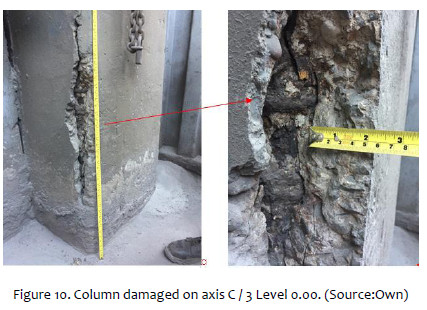
Considering the location near the sea, the moisture due environment, the loss of coating in the elements of reinforced concrete produces rust on the reinforcement, which along time can lose cross section and consequently its structural capacity will be reduced. For the structural analysis, the condition of the elements was taken account and the demand in the damaged elements was assessed.
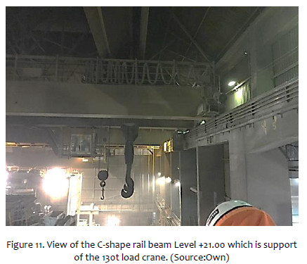
The reinforced concrete beams were screened to verify dimensions and conditions as well as observe how the loads and weights are transmitted from their origin to their foundation. It can be seen in Figure 11 the overhead crane supported on the rail beam of the C axis and the 130t crane.
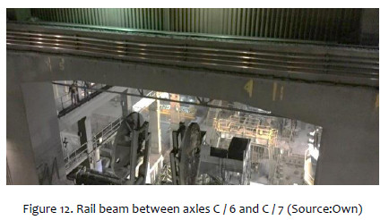
One of the beams where greater emphasis was placed on auscultation was the track beam on Axis C, which loads the heavier cranes, 130tn and 80tn. The section shown in Figure 12 shows the beam with brackets between the axles C / 6 and C / 7. It was observed that the beam has metal plates attached to one side of this and mortar stuck in the bottom. These surfaces were cleaned manually and cracks from 0.20mm to 0.50mm could be noticed, which are not indicative of structural damage. No greater damage is observed in these, only the presence of metallic dust produced by the yielding of metal, as well as some scratches that could occur. with friction of mechanical equipment.
The foundations reinforced in 2006 as well as the original ones are in good condition according to the auscultation carried out. The carrying capacity of the soil is not less than the pressure exerted by the weight of the structure on the foundation. In addition, the structural capacity of the foundation members such as footings and beams is greater than the product demand of all design load combinations according to the Peruvian code.
3. COMPUTATIONAL MODELING
Linear static and dynamic structural analyses were performed using SAP2000 software. Two models were developed, one for the steel roof independently, and other for the concrete structure which carries la load from that roof which was modeled using equivalent members, which replace the trusses of that steel roof.
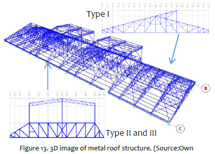
For the computational model to the roof, line elements were used to idealize the elements of the trusses and a 3D model was built, taking special care to add every truss element to have a reliable response of behavior of the structure and its loads transmission.
Besides, it was taken into account the location of every shape on its respective axis and orientation of local axes. It is shown in Figure 13 a 3D view of the structure of the steel roof. Type I truss is made predominantly of hot rolled shapes double angles of 2in flanges and varying thickness depending on whether the element is a bridle, diagonal or stanchion, from 6mm to 3mm. Their connections are with gusset plates welded to these angle shapes. They are between Axes 1 to 4 and 9 to 13. Type II and III trusses are made by a trapezoids area ant the structural shapes by rectangular hollow sections of 6 "x6" x6mm and 6 "x6" x4.5mm for the bridles, 6 "x6" x3mm for the diagonals and stanchion; and another upper part formed by profiles of double angle similar to those of Type I, these supported in tubular profiles 6 "x6" x8mm connected to the lower part. According to the original plans provided by the client. The material used is not specified in the original documents and drawings, therefore it is considered HSS tubes with material ASTM A500 Gr.B and verified using the material property values from coupon tests. These type of truss are located on the Axes 5 to 8. This area is the largest variation of heat product of the steel foundry that occurs in that place, reaching a variation of temperature more than 50-Celsius degrees.
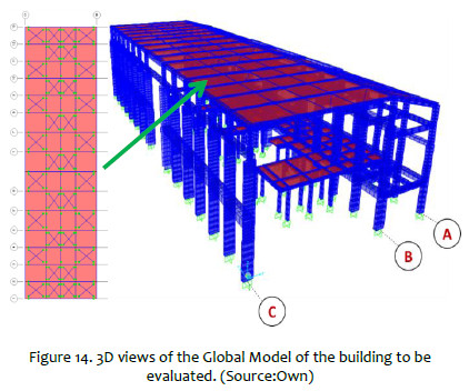
The reinforced concrete structure supports the loads from the roof loads, cranes, and every service loads of the facility. The computer model prepared for reinforced concrete frames is shown Figure 14.
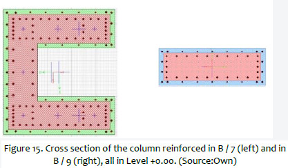
Columns and foundation were reinforced in 2006. Concrete Jackets of 10cm thickness were applied to C and rectangular columns (Figure 15) at Axis 5 to 8 and foundation were expanded, both along Axis B and C.
Besides, there are two main parts for the concrete structure: the plane frame on the Axis C, and a 3D structure between the Axis B and Axis A. The steel roof connects both parts, which behave as a flexural diaphragm.
Regarding the steel roof above the concrete frames, this provides a partially flexible diaphragm as observed in the auscultation as in its analysis. This can distribute forces of gravity and lateral forces according to the axial and flexural rigidity of roof and horizontal elements, especially the naves parallel to the longitudinal direction of the roof and the diagonals in the horizontal plane also of the roof. The elements of this model have axial and flexural rigidity of each roof nave and diaphragm element, maintaining a deformation similar to the 3D roof structure as their Type I and Type II ships observed previously. This modeling was carried out to study the behavior of the concrete structure as-built or in its current state.
The metal trusses were modeled as beam elements between Axis B and C with the characteristics of axial and bending stiffness of the original struts. The Figure 16 and Figure 17 show how the axial and bending stiffness were calculated for the equivalent elements.


Due this modeling procedure, equivalent frames were applied on the computational model. By this way, it is avoiding possible computational problems during the running of the analysis such as large iterations of incongruent results. For effects of deformation on horizontal plan, diagonal steel roads are also applied to the computational model, as show is Figure 14.
4. EVALUATION OF STRUCTURAL MEMBERS AND PERFORMANCE OF MELT SHOP STRUCTURE –
4.1 Linear Static and Dynamic Analysis
It was applied Peruvian provisions for seismic lateral loads from Peruvian provision NTE E030 [5] as well the drift limits and reduction factors. As well, gravity loads were provided from the owner of the facility and the Peru code of loads NTE E020 [6]. Wind loads were applied from Peru code NTE E20 too. For steel design it was applied AISC 360 -10 [7] and AISC 341-10 [8] and for concrete structure the Peru code NTE 060 [9]. LRFD design methodology was used for the structural verification of the steel and concrete members.
Effects made of loads from cranes were calculated using influence line methods for columns, beams and foundations. Besides, it was studied the location for worse case scenarios from crane loads to concrete frames when 2 cranes works at the same time.
Dynamic Modal Spectral Analysis was performed for seismic analysis. The importance coefficient for essential infrastructure was used, since the design philosophy applied to the present evaluation is that the building has to be able to continue operating even after the seismic event. The reduction factor used for steel truss was 4.6 and for the concrete frame 3.6, which carries the load from the steel roof. Seismic mass consisted of 100 % of dead load and 50% of Live Loads. Full load from cranes is also adding the mass since it is considered that seismic event might occurs during production time. P-delta effect is also applied to the lateral structural analysis.
It was found that several of the members of the steel roof would not pass before extraordinary loads (wind and / or earthquake) and ordinary (service) loads: gravity and temperature; that is, the design for current regulations is not adequate and does not comply with these standards. Ratios larger of 1.5 are presented. See Figure 17. The roof is currently standing because the current weight physically applied above the roof is less than the minimum nominal loads of the standard and less than the last loads product of the load combinations with which the design was verified.
Regarding the walkways that are supported on the roof, they represent an increase in weight for gravity loads and an increase in mass for the calculation of seismic forces. It is noticed that the roof structure would not hold additional loads of new pedestrian walkways without previous reinforcement.
It is observed that only on Axis 1 and Axis A for seismic event at the transversal direction, the drift is 0.71% which is greater than the 0.7% that is the limit established by NTE 030 for buildings. For other Axis and levels, and directions, drifts are around 0.55%. Because it is an infrastructure for industrial use, the definition of height of the mezzanine, inter-story height is not clearly defined if there is no slab as in the interception of Axis A and Axis 1. Therefore, the Peruvian seismic code mentions that for industries, the limit may be greater than 0.7% but should not exceed double. For no extreme case of lateral displacements, this limit is reached, the highest drift being 0.71% lower than the 2x0.7%. Even so, due to the long deflection presented, it is expected that the column in such a location will have a high demand in flexion that will be evaluated.
Under design loads, the structural elements of concrete beams and columns have larger capacity than their respectively demands, see Figure 18 and Figure 19 for axial – bending verification. However, there are only a few elements of beams and columns that fail due to bending and shear effects for load combinations that include combined dead, live and earthquake loads (1.25DL + 1.25LL + 1E and 0.9DL + 1E) including dead loads and live induced by the bridge crane when it is in operation with the full bucket, that is, it is expected that these elements fail when an earthquake occurs and the overhead cranes are in operation with full buckets. The faults that are expected in this event are shear failures for at C/6 and C/7 and B/6 and B7 columns and bending in the roof beams located between Axis A and B transverse direction. Slenderness and large displacement for columns are considered since they are carrying heavy gravity service loads out and large lateral displacements.
Lap splices applied to the original construction were retrofitted during 2006 work for the columns with new jackets. Beams not present short lap splices for bending neither shear effects.
Spacing of stirrups on non-retrofitted columns and beams are larger than current provisions demand. Besides for shear capacity beams of 14m shows around 10% higher demand than capacity.
4.2 Non Linear Static Analysis
For the calculation of the capacity curves for each infrastructure, the non-linear properties of the materials, both steel and concrete, were considered. The results of the concrete core tests were used to calculate the non-linear behavior of columns and beams. In addition, the confinement applied to the columns was also considered since this effect produces a greater capacity of them, increasing their response to compression depending on the number of stirrups used according to Mander et.al. [10]
Since the steel roof does not behave like a rigid diaphragm, we proceeded to analyze the infrastructure having equivalent members for the steel truss according to transverse and longitudinal deflections. Axial and bending stiffness were calculated to obtain these equivalent members as explained at section 3. Then the capacity of structure the can be calculated achieving accurate approximation. That is possible because of reducing computational errors due the applied numerical methods; as well avoiding larger amount of members which is recommendable for this type of non-linear analysis.
For the non-linear model of each of the two parts of the infrastructure, the provisions of ASCE 41-16 [11] were used for the behavior pattern with idealized curves of moment-curvature and force-deformation. For the columns we proceeded to calculate, using the fiber method, the curvature moment curves for the plastic hinges in the columns and then idealize them with bi-linear behavior, also shear hinges were developed as ASCE 41-16[11] provisions indicates. In the case of the beams, moment curvature and shear behavior parameters were established by bilinear and tri lineal behavior of beams that do not contain greater axial force as ASCE 41-16 [11] provides.
The seismic demand is characterized using the elastic response spectrum of acceleration for a damping of 5% corresponding to the concrete, which must be transformed to an ADRS format Acceleration Displacement Response Spectrum as ATC-40 procedures [12] that is, spectral acceleration (Sa as a fraction of the acceleration of gravity g) with respect to the spectral pseudo displacement (Sd) and then Shear Base vs. Drift.
Besides, reading the response from center of mass on the roof it is not suitable for this type of structure since it has a no rigid diaphragm. Therefore it was reading response from frame on Axis C separately with the frame of Axis B and A. It is presented the case which presents worse scenario of response.
It can be seen in Figure 20 the performance response of frame at Axis C on longitudinal direction of the infrastructure. For drift response, it will develop in the non-linear range of behavior. This corresponds to the results obtained from dynamic linear analysis. By demand in bending, the frame of the Axis C would have an adequate behavior to an earthquake event like the one described, even so by cutting it has to be considered a reinforcement.
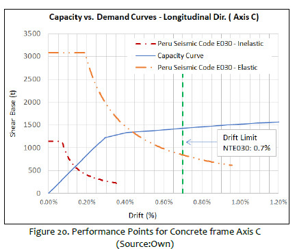
For shear base performance, the structure will be in a linear performance. It is observed that upon reaching the horizontal inelastic displacement limit of the seismic code, the structure would be in the non-linear range, where structural damage could occur such as cracking and spalling of cover, however it will not collapse and no major structural damage is expected.
CONCLUSIONS
The integrity of the full structure of the melt-shop under seismic loads was analyzed. Lateral displacements due seismic loads based on Peruvian provisions are allowed. Nevertheless, It was noticed that the concrete frames would reach nonlinear behavior under seismic demand due Peru codes as well.
Due high temperatures, quality of steel material was not changed significally because of it protection by paint; however concrete strength presented a reduction especially at columns and beams near the melt oven.
It is necessary repair local damage on concrete members where spalling of cover and rust on reinforced are presented. As well it is necessary to retrofit the columns and beams which demands are higher than capacity of bending and shear. Under the heavy loads from the 3 cranes is OK the concrete frames, however due seismic loads the columns and beams might fail. Using CFRP is one alternative for retrofit.
Maintenance of the steel roof should be applied. Removing the metal dust will reduce the existing weight on the steel shapes. Besides it is necessary to reinforce the steel members, adding lateral braces is an option.
Old Structures should be assessed specially if its use compromise live of the users and verify cost-benefits of the stakeholders to keep them or replace for new infrastructure.
ACKNOWLEDGEMENT
Authors would like to acknowledge to people of HATCH for their support at logistic of the project.
REFERENCES
[1] American Standard Test Method s, ASTM Method for Obtaining and Testing Drilled Cores and Sawed Beams of Concrete ASTM C42. [ Links ]
[2] American Standard Test Method s, ASTM Method for Obtaining and Testing Drilled Cores and Sawed Beams of Concrete ASTM C805. [ Links ]
[3] American Institute of Steel Construction, AISC Steel Construction Manual 14 th Edition [ Links ]
[4] American Standard Test Method s, ASTM Method for Test Coupons for Steel Castings ASTM C1067. [ Links ]
[5] Peru Seismic Load Provisions 2016 Norma Técnica de Estructuras, Diseño Sismoresistente NTE 030 [ Links ]
[6] Peru Gravity and Wind Load Provisions Norma Técnica de Estructuras, Diseño Sismoresistente NTE 020 [ Links ]
[7] American Institute of Steel Construction, AISC 360-10 Specification for Structural Steel Buildings [ Links ]
[8] American Institute of Steel Construction, AISC 341-10 Seismic Provisions for Structural Steel Buildings [ Links ]
[9] Norma Técnica de Estructuras 2009Concreto Armado NTE 060 [ Links ]
[10] Mander J B, Priestley M J N and Park R 1988 Theoretical Stress-Strain Model for Confined Concrete, Journal of Structural Engineering, ASCE 114(8) [ Links ]
[11] American Society of Civil Engineers – Structural Engineering Institute, ASCE41-16/SEI, Seismic Rehabilitation of Existing Buildings, Reston, Virginia. EEUU [ Links ]
[12] Applied Technology Council 1996 ATC-40, Seismic Evaluation and Retrofit of Concrete Building, Technical Report, Redwood City, California [ Links ]
* Corresponding author:
Received: 22/07/2019
Accepted: 14/08/2019

