


 Inglês (pdf)
 Artigo em XML
 Referências do artigo
 Enviar este artigo por email
 Citado por SciELO
  Similares em
SciELO
Similares em
SciELO 
 Permalink
1. INTRODUCTION
In countries with high seismic activity, such as Peru, the structural design of buildings is governed by seismic forces. However, while current design standards guarantee that buildings will not collapse in the event of a severe earthquake, they do not guarantee avoiding structural and non-structural damage [1].
The use of energy dissipators is presented as a viable alternative to the current philosophy of structural design that is based on admitting a certain level of damage in a severe earthquake [2]. Energy dissipators are devices that increase the energy dissipation capability of the building to which they are attached by conversion of mechanical energy into heat energy; thus, causing less damage to structural elements [3].
The main advantage of energy dissipators is that they allow the reduction of seismic demand on the main structure and concentrate the damage in previously identified points or elements. In addition, these devices are activated at low velocities and displacements, can be placed in existing buildings and develop stable hysterical behaviors. However, hysteretic dampers (HD) have the disadvantage that they may require replacement after a severe earthquake, while the downside of fluid viscous dampers (FVD) could suffer from fluid seal leakage (reliability concern) [4].
An important aspect to consider within the structural design of buildings with energy dissipators is the dimensioning of these devices. Currently, there are no standardized procedures to carry out this process; thus, dimensioning of energy dissipators ends up being in many cases the result of a trial-and-error procedure [5].
This research aims to determine the efficiency of energy dissipators, both fluid viscous and hysteretic, quantifying to what extent the seismic responses of buildings, such as displacements, velocities, and accelerations, are reduced. This would provide new tools to engineers in order to make correct decisions in the process of selecting the type of seismic protection system to use. In addition, a procedure is proposed for the dimensioning of hysterical dampers, which will help to overcome the aforementioned trial-and-error approach.
2. ENERGY DISSIPATORS AND SEISMIC LOADS
2.1 ENERGY DISSIPATION DEVICES
Two different types of energy dissipators were studied in this research. On the one hand, the FVDs (Fig. 1a), which increase the damping of the structure without increasing the stiffness and whose operation depends fundamentally on the relative velocity of its ends. On the other hand, the HDs (Fig. 1b), which are metallic devices that are inserted into structure and are capable of deforming in the inelastic range, allowing them to absorb and dissipate energy through a hysterical process.
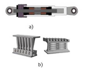
Fig. 1 Energy dissipators. (a) Fluid viscous damper (Taylor), (b) Hysteretic dampers (TADAS and SLB).
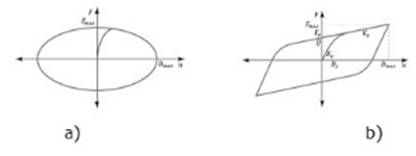
A mathematical model, in which the force is proportional to the relative velocity, was used for the hysteresis of the FVDs. Likewise, the Bouc-Wen model was used to predict the non-linear dynamic behavior of hysteretic dampers. Fig. 2 shows the force-displacement relationship for both dissipators.
2.2 SEISMIC RECORDS
Three different seismic records, obtained from REDACIS (CISMID-UNI strong motion network) and RENADIC (national strong motion network of Chile), were used in this research, which share the characteristic of coming from large-magnitude subduction earthquakes. Band-pass frequency filtering and baseline correction were applied to both components of each seismic record. Subsequently, the records were scaled by spectral matching, the target spectrum being the one given by the Peruvian standard E031 [10], with Z = 0.45, U = 1 and S = 1 (where Z, U and S are factors for zone, use or importance and soil amplification, respectively).
TABLE I shows the most important characteristics of the seismic records.
TABLE I Characteristics of the three seismic records considered
| Earthquake | Station | Source | Date | # Points | dt [s] | Component | Original PGA [g] | Scaled PGA [g] | |||
|---|---|---|---|---|---|---|---|---|---|---|---|
| Lima 1966 | Parque de la Reserva | REDACIS | 10/17/1966 | 3283 | 0.02 | NS | 0.26 | 0.82 | EW | 0.18 | 0.69 |
| Pisco 2007 | UNICA | REDACIS | 08/15/2007 | 21807 | 0.01 | NS | 0.33 | 0.67 | EW | 0.27 | 0.59 |
| Maule 2010 | Constitución | RENADIC | 02/27/2010 | 28657 | 0.005 | L | 0.52 | 0.61 | T | 0.61 | 0.66 |
3. DIMENSIONING OF ENERGY DISSIPATORS
3.1 DIMENSIONING OF FLUID VISCOUS DAMPERS
The procedure proposed by Silvestri et. al [5] was used for dimensioning the FVDs in this research, both in the case of simplified models and for an existing building. This procedure is characterized by being a simple and practical guide that helps from the choice of a target reduction in the seismic responses to the identification of the mechanical characteristics of the dissipators.
3.2 DIMENSIONING OF HYSTERETIC DAMPERS
In this research, a procedure is proposed for the dimensioning of the mechanical characteristics of the HDs that will be placed in a building. This procedure was evaluated with satisfactory results [11] and consists of the following four steps:
(1)3.2.1 Step 1: Identification of the target reduction factor
The target reduction factor (η) is the ratio of the seismic response of the system with and without hysteretic dampers. For instance, equation (1) shows the target reduction factor with reference to the story drift response.
3.2.2 Step 2: Time history analysis of the building without hysteretic dampers
The analysis is carried out to obtain the shear forces of each story (V i ), the basal shear force (V b ) and the stiffness of each level (K i ).
(2)3.2.3 Step 3: Identification of the characteristics of nonlinear hysteretic dampers
The parameters that define the Bouc-Wen hysterical behavior of the HDs of each of the levels are calculated with equation (2).
where λ1 and λ2 are factors that are obtained from Fig. 3 once the target reduction factor has been established and n is the number of levels in the building.
3.2.4 Step 4: Final nonlinear time history analysis
A final nonlinear time history analysis is performed considering the incorporation of hysteretic dampers, in order to calculate the seismic responses and verify if the target reduction factor of Step 1 was achieved.
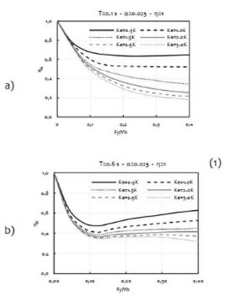
Fig. 3 is the result of performing many time-history analyses on simplified models of n DOF (degree of freedom) that incorporate hysteretic dampers with nonlinear behavior (such as those in section 4 of this research). For these analyses, the NS component of the Lima 1966 seismic record has been used as ground acceleration. In
Fig. 3, only the results for buildings with 1 and 6 levels are shown; however, similar graphs can be made for buildings with a different number of levels [11].
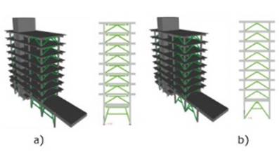
(3)4. SIMPLIFIED MODELS OF BUILDINGS WITH ENERGY DISSIPATORS
Fig. 4 shows two-dimensional models of buildings with viscous fluid and hysteretic dampers. The simplified models consist of masses and springs with linear and elastic behavior whose properties, such as mass and stiffness, are obtained from a shear beam model, joined by link elements with non-linear behavior to simulate energy dissipators [11].
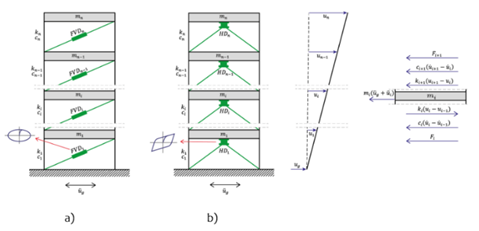
From the previous image the following matrix equation is obtained:
In equation (3), M and K are the n-dimensional matrices of mass and stiffness of the structure, C is the damping matrix (obtained according to Rayleigh's theory [12]), u is a vector that collects the lateral displacements and τ is the n×1 influence vector of the structure associated with the ground motion, u ̈_g. Furthermore, F is a vector related to the forces developed by the energy dissipators, being:

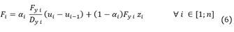 The value of F_i in equation (4) varies depending on the type of energy that dissipators used, equation ¡Error! No se encuentra el origen de la referencia.) for FVDs and equation ¡Error! No se encuentra el origen de la referencia.) for HDs.
Using numerical integration algorithms (central difference [13] for buildings with FVDs and Runge-Kutta [14] for buildings with HDs) it is possible to calculate the time histories of the seismic responses, such as base shear and top floor displacement and acceleration.
5. AN EXISTING BUILDING
The research case study is the main building of the Lima airport called Jorge Chavez, which was designed and built in the 1960s. The original design was here considered although this building later was retrofitted. It has 10 floors, with a total height of 45 meters. The structural system of this building consists of post-tensioned reinforced concrete frames and shear walls (due to the elevator shaft). It also has a rectangular shape in plan, with greater stiffness in the longitudinal direction than in the transverse direction. Consequently, the main structural problems detected are: torsional irregularity and excessive flexibility in the transverse direction [15].
Two alternatives are proposed to improve the seismic behavior of this building, the first using FVDs and the second incorporating HDs. Both alternatives seek to reduce the story drift to the value of 7 ‰, which is the limit given by the Peruvian standard E030. The results presented are for the transversal direction since it is the most critical.
The structural models in all cases were made using the ETABS software. Fig. 5a and Fig. 5b show the structural models of the building with FVDs and HDs, respectively.
The energy dissipators, in both cases installed at all floors, were modeled using link elements with non-linear behavior. The FVDs were placed in a Chevron arrangement with two devices per structural axis, for a total of four devices per floor. While the HDs were placed in a serial configuration with three devices per structural axis, making a total of six devices per floor. On the other hand, dimensioning of both types of energy dissipators was carried out for a target reduction factor of
(5)6. RESULTS AND DISCUSSION
The efficiency of energy dissipators is understood as their ability to reduce seismic responses when they are incorporated into a building. The response reduction (
6.1 TWO-DIMENSIONAL SIMPLIFIED MODELS
By fixing the fundamental period and the number of floors of the building and also considering that its behavior is close to a shear beam, the dynamic properties used to form the equivalent simplified model of this building are obtained ([11], [16]). Likewise, the parameters that characterize the nonlinear behavior of the energy dissipators are obtained through the procedures described in Section 3 of this paper.
Using the aforementioned simplified models, a series of nonlinear time history analyzes were carried out for buildings with a different number of floors and with different target reduction factors. For this, it was considered that the fundamental period of the building as T=0.1n and in all cases only the spectrally matched record of the NS component of the Lima 1966 earthquake was used. Then, using equation (5), seismic response reduction for the base shear and the displacement and acceleration of the top floor was calculated.
In Fig. 6 the reductions of the seismic responses for buildings with FVDs are presented. In all cases a magnification factor
It should be noted that Fig. 6a and Fig. 6b show that for low values of target reduction factor,
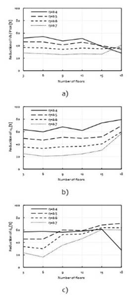
Fig. 6 Reductions in seismic responses in buildings with FVDs. (a) Base shear, (b) Top floor displacement, (c) Top floor acceleration.
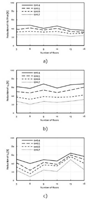
Fig. 7 Reductions in seismic responses in buildings with HDs. (a) Base shear, (b) Top floor displacement, (c) Top floor acceleration.
From Fig. 6 and Fig. 7, it is concluded that the use of FVDs and HDs allows reducing the seismic responses of buildings. These reductions are, in most cases, independent of the number of floors and indirectly proportional to the target reduction factor. However, in buildings with FVDs using very low values of
6.2 EXISTING BUILDING MODEL
6.2.1 Building without energy dissipators
With the ETABS model of the main building of the Jorge Chavez airport, a series of nonlinear time history analyzes were carried out using the three seismic records shown in TABLE I as ground acceleration. In Fig. 8 the story drifts and the displacement of the said building are observed, where it can be seen that the story drifts widely exceed the limit of 7 ‰.

6.2.2 Building with FVDs
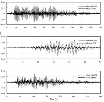
After incorporating the FVDs, a great reduction in seismic responses is evidenced. Fig. 9 shows the lateral displacements and story drifts, which are below the target limit. Likewise, Fig. 10 shows the displacement of the top floor, comparing the results with and without FVDs.
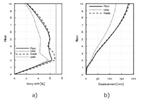
Fig. 9 Seismic responses of the Jorge Chavez building with FVDs. (a) Story drifts, (b) Lateral displacements.
6.2.3 Building with HDs
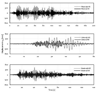
By incorporating DHs in the building, a significant reduction in seismic responses is also evidenced. Fig. 11. presents the lateral displacements and story drifts where it is observed that the drifts are below the target limit. Furthermore, Fig. 12 shows the displacement of the top floor, comparing the alternatives with and without HDs.
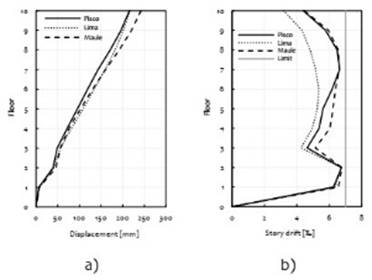
Fig. 11 Seismic responses of the Jorge Chavez building with HDs. (a) Story drifts, (b) Lateral displacements.
6.3 COMPARISON BETWEEN SIMPLIFIED MODEL AND 3D MODEL RESULTS
TABLE II and TABLE III compare the reduction percentages of the seismic responses obtained with the three-dimensional model in ETABS and those obtained with the simplified model. In TABLE II it can be seen that both models have similar reduction values for all responses. However, in TABLE III it is observed that there are similar values only in terms of the reduction in displacement, since the reductions in accelerations and base shears are very different.
In the case of buildings with HDs, the simplified models show positive reductions, while the ETABS model has negative values. This indicates that in the 3D model the acceleration and total base shear values are higher with HDs than without HDs. This is because HDs provide additional stiffness to the building. However, it is important to clarify that even when the total base shear force of the building with DHs is higher, a large part of this force is absorbed by the DHs and the main structure (the one to be protected) receives a small percentage of it.
TABLE II Reductions in seismic responses in the building with FVDs
| Reductions in Seismic Responses [%] | |||
| Model | u10 | ü10 | Vb |
| ETABS | 63 | 60 | 56 |
| Simplified | 66 | 57 | 49 |
CONCLUSIONS
The simplified models allow a quick and acceptable prediction of the levels of reduction of the seismic response that can be achieved in three-dimensional reinforced concrete buildings that incorporate energy dissipators.
A procedure was proposed for the dimensioning of hysterical dampers that will be incorporated into a building. The graphs used in this procedure are the result of performing a series of nonlinear time history analyzes on simplified models of buildings with hysteretic dampers that have a Bouc Wen hysterical behavior.
As shown in Fig. 6 and Fig. 7, there is a limitation regarding the reductions that can be achieved using energy dissipators (both fluid viscous dampers and hysteretic dampers), said maximum reductions being in the range of 50% and 70% approximately.
The target reduction factor (
Hysteretic dampers reduce story drifts and lateral displacements in buildings. However, as the results of the three-dimensional model of the Jorge Chavez airport building show, in certain cases the addition of hysteretic dampers increases the accelerations and the total base shear force of the structure. However, it must be specified that even when the total base shear increases, the effective base shear force received by the main structure is lower compared to the alternative without dissipators, since a large part of the shear is absorbed by the hysteretic dampers.

